|
a. Various types of air navigation aids are in use today, each serving a special purpose. These aids have varied owners and operators, namely: the Federal Aviation Administration (FAA), the military services, private organizations, individual states and foreign governments. The FAA has the statutory authority to establish, operate, maintain air navigation facilities and to prescribe standards for the operation of any of these aids which are used for instrument flight in federally controlled airspace. These aids are tabulated in the Airport/Facility Directory (A/FD). b. Pilots should be aware of the possibility of momentary erroneous indications on cockpit displays when the primary signal generator for a ground-based navigational transmitter (for example, a glideslope, VOR, or nondirectional beacon) is inoperative. Pilots should disregard any navigation indication, regardless of its apparent validity, if the particular transmitter was identified by NOTAM or otherwise as unusable or inoperative. 1-1-2. Nondirectional Radio Beacon (NDB) a. A low or medium frequency radio beacon transmits nondirectional signals whereby the pilot of an aircraft properly equipped can determine bearings and "home" on the station. These facilities normally operate in a frequency band of 190 to 535 kilohertz (kHz), according to ICAO Annex 10 the frequency range for NDBs is between 190 and 1750 kHz, and transmit a continuous carrier with either 400 or 1020 hertz (Hz) modulation. All radio beacons except the compass locators transmit a continuous three-letter identification in code except during voice transmissions. b. When a radio beacon is used in conjunction with the Instrument Landing System markers, it is called a Compass Locator. c. Voice transmissions are made on radio beacons unless the letter "W" (without voice) is included in the class designator (HW). d. Radio beacons are subject to disturbances that may result in erroneous bearing information. Such disturbances result from such factors as lightning, precipitation static, etc. At night, radio beacons are vulnerable to interference from distant stations. Nearly all disturbances which affect the Automatic Direction Finder (ADF) bearing also affect the facility's identification. Noisy identification usually occurs when the ADF needle is erratic. Voice, music or erroneous identification may be heard when a steady false bearing is being displayed. Since ADF receivers do not have a "flag" to warn the pilot when erroneous bearing information is being displayed, the pilot should continuously monitor the NDB's identification. 1-1-3. VHF Omni-directional Range (VOR) a. VORs operate within the 108.0 to 117.95 MHz frequency band and have a power output necessary to provide coverage within their assigned operational service volume. They are subject to line-of-sight restrictions, and the range varies proportionally to the altitude of the receiving equipment. NOTE- b. Most VORs are equipped for voice transmission on the VOR frequency. VORs without voice capability are indicated by the letter "W" (without voice) included in the class designator (VORW). c. The only positive method of identifying a VOR is by its Morse Code identification or by the recorded automatic voice identification which is always indicated by use of the word "VOR" following the range's name. Reliance on determining the identification of an omnirange should never be placed on listening to voice transmissions by the Flight Service Station (FSS) (or approach control facility) involved. Many FSSs remotely operate several omniranges with different names. In some cases, none of the VORs have the name of the "parent" FSS. During periods of maintenance, the facility may radiate a T-E-S-T code (- D DDD -) or the code may be removed. d. Voice identification has been added to numerous VORs. The transmission consists of a voice announcement, "AIRVILLE VOR" alternating with the usual Morse Code identification. e. The effectiveness of the VOR depends upon proper use and adjustment of both ground and airborne equipment. 1. Accuracy. The accuracy of course alignment of the VOR is excellent, being generally plus or minus 1 degree. 2. Roughness. On some VORs, minor course roughness may be observed, evidenced by course needle or brief flag alarm activity (some receivers are more susceptible to these irregularities than others). At a few stations, usually in mountainous terrain, the pilot may occasionally observe a brief course needle oscillation, similar to the indication of "approaching station." Pilots flying over unfamiliar routes are cautioned to be on the alert for these vagaries, and in particular, to use the "to/from" indicator to determine positive station passage. (a) Certain propeller revolutions per minute (RPM) settings or helicopter rotor speeds can cause the VOR Course Deviation Indicator to fluctuate as much as plus or minus six degrees. Slight changes to the RPM setting will normally smooth out this roughness. Pilots are urged to check for this modulation phenomenon prior to reporting a VOR station or aircraft equipment for unsatisfactory operation. a. The FAA VOR test facility (VOT) transmits a test signal which provides users a convenient means to determine the operational status and accuracy of a VOR receiver while on the ground where a VOT is located. The airborne use of VOT is permitted; however, its use is strictly limited to those areas/altitudes specifically authorized in the A/FD or appropriate supplement. b. To use the VOT service, tune in the VOT frequency on your VOR receiver. With the Course Deviation Indicator (CDI) centered, the omni-bearing selector should read 0 degrees with the to/from indication showing "from" or the omni-bearing selector should read 180 degrees with the to/from indication showing "to." Should the VOR receiver operate an RMI (Radio Magnetic Indicator), it will indicate 180 degrees on any omni-bearing selector (OBS) setting. Two means of identification are used. One is a series of dots and the other is a continuous tone. Information concerning an individual test signal can be obtained from the local FSS. c. Periodic VOR receiver calibration is most important. If a receiver's Automatic Gain Control or modulation circuit deteriorates, it is possible for it to display acceptable accuracy and sensitivity close into the VOR or VOT and display out-of-tolerance readings when located at greater distances where weaker signal areas exist. The likelihood of this deterioration varies between receivers, and is generally considered a function of time. The best assurance of having an accurate receiver is periodic calibration. Yearly intervals are recommended at which time an authorized repair facility should recalibrate the receiver to the manufacturer's specifications. d. Federal Aviation Regulations (14 CFR Section 91.171) provides for certain VOR equipment accuracy checks prior to flight under instrument flight rules. To comply with this requirement and to ensure satisfactory operation of the airborne system, the FAA has provided pilots with the following means of checking VOR receiver accuracy: 1. VOT or a radiated test signal from an appropriately rated radio repair station. 2. Certified airborne check points. 3. Certified check points on the airport surface. e. A radiated VOT from an appropriately rated radio repair station serves the same purpose as an FAA VOR signal and the check is made in much the same manner as a VOT with the following differences: 1. The frequency normally approved by the Federal Communications Commission is 108.0 MHz. 2. Repair stations are not permitted to radiate the VOR test signal continuously; consequently, the owner or operator must make arrangements with the repair station to have the test signal transmitted. This service is not provided by all radio repair stations. The aircraft owner or operator must determine which repair station in the local area provides this service. A representative of the repair station must make an entry into the aircraft logbook or other permanent record certifying to the radial accuracy and the date of transmission. The owner, operator or representative of the repair station may accomplish the necessary checks in the aircraft and make a logbook entry stating the results. It is necessary to verify which test radial is being transmitted and whether you should get a "to" or "from" indication. f. Airborne and ground check points consist of certified radials that should be received at specific points on the airport surface or over specific landmarks while airborne in the immediate vicinity of the airport. 1. Should an error in excess of plus or minus 4 degrees be indicated through use of a ground check, or plus or minus 6 degrees using the airborne check, Instrument Flight Rules (IFR) flight shall not be attempted without first correcting the source of the error. CAUTION- 2. Locations of airborne check points, ground check points and VOTs are published in the A/FD and are depicted on the A/G voice communications panels on the FAA IFR area chart and IFR enroute low altitude chart. 3. If a dual system VOR (units independent of each other except for the antenna) is installed in the aircraft, one system may be checked against the other. Turn both systems to the same VOR ground facility and note the indicated bearing to that station. The maximum permissible variations between the two indicated bearings is 4 degrees. 1-1-5. Tactical Air Navigation (TACAN) a. For reasons peculiar to military or naval operations (unusual siting conditions, the pitching and rolling of a naval vessel, etc.) the civil VOR/Distance Measuring Equipment (DME) system of air navigation was considered unsuitable for military or naval use. A new navigational system, TACAN, was therefore developed by the military and naval forces to more readily lend itself to military and naval requirements. As a result, the FAA has integrated TACAN facilities with the civil VOR/DME program. Although the theoretical, or technical principles of operation of TACAN equipment are quite different from those of VOR/DME facilities, the end result, as far as the navigating pilot is concerned, is the same. These integrated facilities are called VORTACs. b. TACAN ground equipment consists of either a fixed or mobile transmitting unit. The airborne unit in conjunction with the ground unit reduces the transmitted signal to a visual presentation of both azimuth and distance information. TACAN is a pulse system and operates in the Ultrahigh Frequency (UHF) band of frequencies. Its use requires TACAN airborne equipment and does not operate through conventional VOR equipment. 1-1-6. VHF Omni-directional Range/Tactical Air Navigation (VORTAC) a. A VORTAC is a facility consisting of two components, VOR and TACAN, which provides three individual services: VOR azimuth, TACAN azimuth and TACAN distance (DME) at one site. Although consisting of more than one component, incorporating more than one operating frequency, and using more than one antenna system, a VORTAC is considered to be a unified navigational aid. Both components of a VORTAC are envisioned as operating simultaneously and providing the three services at all times. b. Transmitted signals of VOR and TACAN are each identified by three-letter code transmission and are interlocked so that pilots using VOR azimuth with TACAN distance can be assured that both signals being received are definitely from the same ground station. The frequency channels of the VOR and the TACAN at each VORTAC facility are "paired" in accordance with a national plan to simplify airborne operation. 1-1-7. Distance Measuring Equipment (DME) a. In the operation of DME, paired pulses at a specific spacing are sent out from the aircraft (this is the interrogation) and are received at the ground station. The ground station (transponder) then transmits paired pulses back to the aircraft at the same pulse spacing but on a different frequency. The time required for the round trip of this signal exchange is measured in the airborne DME unit and is translated into distance (nautical miles) from the aircraft to the ground station. b. Operating on the line-of-sight principle, DME furnishes distance information with a very high degree of accuracy. Reliable signals may be received at distances up to 199 NM at line-of-sight altitude with an accuracy of better than 1/2 mile or 3 percent of the distance, whichever is greater. Distance information received from DME equipment is SLANT RANGE distance and not actual horizontal distance. c. Operating frequency range of a DME according to ICAO Annex 10 is from 960 MHz to 1215 MHz. Aircraft equipped with TACAN equipment will receive distance information from a VORTAC automatically, while aircraft equipped with VOR must have a separate DME airborne unit. d. VOR/DME, VORTAC, Instrument Landing System (ILS)/DME, and localizer (LOC)/DME navigation facilities established by the FAA provide course and distance information from collocated components under a frequency pairing plan. Aircraft receiving equipment which provides for automatic DME selection assures reception of azimuth and distance information from a common source when designated VOR/DME, VORTAC, ILS/DME, and LOC/DME are selected. e. Due to the limited number of available frequencies, assignment of paired frequencies is required for certain military noncollocated VOR and TACAN facilities which serve the same area but which may be separated by distances up to a few miles. f. VOR/DME, VORTAC, ILS/DME, and LOC/DME facilities are identified by synchronized identifications which are transmitted on a time share basis. The VOR or localizer portion of the facility is identified by a coded tone modulated at 1020 Hz or a combination of code and voice. The TACAN or DME is identified by a coded tone modulated at 1350 Hz. The DME or TACAN coded identification is transmitted one time for each three or four times that the VOR or localizer coded identification is transmitted. When either the VOR or the DME is inoperative, it is important to recognize which identifier is retained for the operative facility. A single coded identification with a repetition interval of approximately 30 seconds indicates that the DME is operative. g. Aircraft equipment which provides for automatic DME selection assures reception of azimuth and distance information from a common source when designated VOR/DME, VORTAC and ILS/DME navigation facilities are selected. Pilots are cautioned to disregard any distance displays from automatically selected DME equipment when VOR or ILS facilities, which do not have the DME feature installed, are being used for position determination. 1-1-8. Navigational Aid (NAVAID) Service Volumes a. Most air navigation radio aids which provide positive course guidance have a designated standard service volume (SSV). The SSV defines the reception limits of unrestricted NAVAIDs which are usable for random/unpublished route navigation. b. A NAVAID will be classified as restricted if it does not conform to flight inspection signal strength and course quality standards throughout the published SSV. However, the NAVAID should not be considered usable at altitudes below that which could be flown while operating under random route IFR conditions (14 CFR Section 91.177), even though these altitudes may lie within the designated SSV. Service volume restrictions are first published in Notices to Airmen (NOTAMs) and then with the alphabetical listing of the NAVAIDs in the A/FD. c. Standard Service Volume limitations do not apply to published IFR routes or procedures. d. VOR/DME/TACAN Standard Service Volumes (SSV). 1. Standard
service volumes (SSVs) are graphically shown in
FIG
1-1-1, FIG
1-1-2, EXAMPLE-
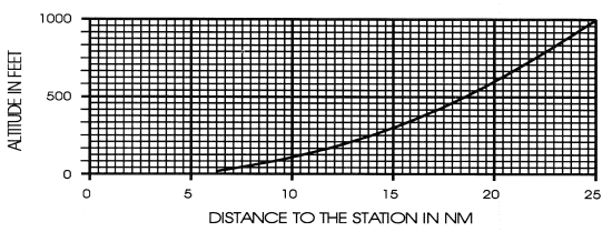
Standard High Altitude Service Volume (See FIG 1-1-5 for altitudes below 1,000 feet). 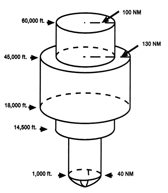
Standard Low Altitude Service Volume (See FIG 1-1-5 for altitudes below 1,000 feet). |
||||||||||||||||||||||||||||||||||||||||||||||||||||||||||||||||||||||||||||||||||||||||||||||||||||||||||||||||||||||||||||||||||||||||||||||||||||||||||||||||||||||||||||||||||||||||||||||||||||||||||||||||||||||||||||||||||||||||||||||||||||||||||||||||||||||||||||||
|
|
|
|
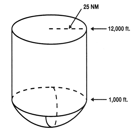
T (Terminal) |
From 1,000 feet above ground level (AGL) up to and including 12,000 feet AGL at radial distances out to 25 NM. |
|
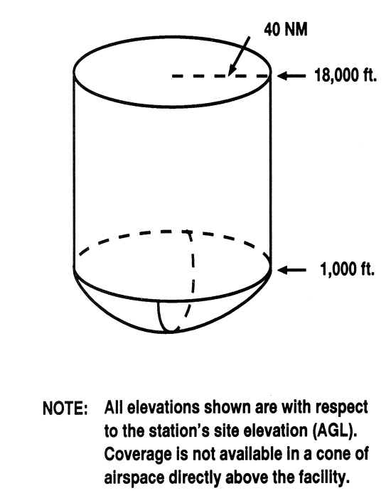
L (Low Altitude) |
From 1,000 feet AGL up to and including 18,000 feet AGL at radial distances out to 40 NM. |
|
H (High Altitude) |
From 1,000 feet AGL up to and including 14,500 feet AGL at radial distances out to 40 NM. From 14,500 AGL up to and including 60,000 feet at radial distances out to 100 NM. From 18,000 feet AGL up to and including 45,000 feet AGL at radial distances out to 130 NM. |
NDB Service Volumes
|
|
|
|
|
|
|
|
|
|
|
|
|
|
|
|
*Service ranges of individual facilities may be less than 50 nautical miles (NM). Restrictions to service volumes are first published as a Notice to Airmen and then with the alphabetical listing of the NAVAID in the A/FD. |
|
FIG
1-1-4
Service Volume Lower Edge Terminal
Service Volume Lower Edge Terminal
FIG
1-1-5
Service Volume Lower Edge
Standard High and Low
Service Volume Lower Edge
Standard High and Low
1-1-9. Instrument Landing System (ILS)
a. General
1. The ILS is designed to provide an approach path for exact alignment and descent of an aircraft on final approach to a runway.
2. The ground equipment consists of two highly directional transmitting systems and, along the approach, three (or fewer) marker beacons. The directional transmitters are known as the localizer and glide slope transmitters.
3. The system may be divided functionally into three parts:
(a) Guidance information: localizer, glide slope;
(b) Range information: marker beacon, DME; and
(c) Visual information: approach lights, touchdown and centerline lights, runway lights.
4. Precision radar, or compass locators located at the Outer Marker (OM) or Middle Marker (MM), may be substituted for marker beacons. DME, when specified in the procedure, may be substituted for the OM.
5. Where a complete ILS system is installed on each end of a runway; (i.e., the approach end of Runway 4 and the approach end of Runway 22) the ILS systems are not in service simultaneously.
b. Localizer
1. The localizer transmitter operates on one of 40 ILS channels within the frequency range of 108.10 to 111.95 MHz. Signals provide the pilot with course guidance to the runway centerline.
2. The approach course of the localizer is called the front course and is used with other functional parts, e.g., glide slope, marker beacons, etc. The localizer signal is transmitted at the far end of the runway. It is adjusted for a course width of (full scale fly-left to a full scale fly-right) of 700 feet at the runway threshold.
3. The course line along the extended centerline of a runway, in the opposite direction to the front course is called the back course.
CAUTION-
Unless the aircraft's ILS equipment includes reverse sensing
capability, when flying inbound on the back course it is
necessary to steer the aircraft in the direction opposite
the needle deflection when making corrections from
off-course to on-course. This "flying away from the needle"
is also required when flying outbound on the front course of
the localizer. Do not use back course signals for approach
unless a back course approach procedure is published for
that particular runway and the approach is authorized by
ATC.
4. Identification is in International Morse Code and consists of a three-letter identifier preceded by the letter I (DD) transmitted on the localizer frequency.
EXAMPLE-
I-DIA
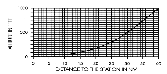
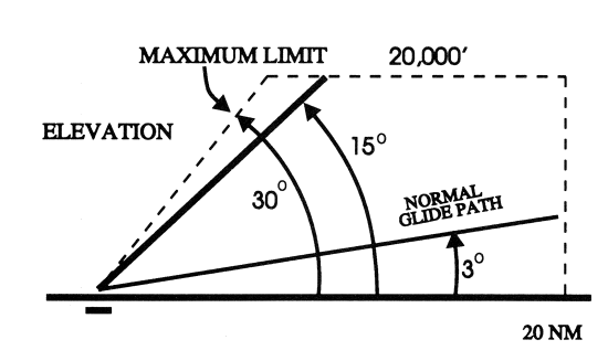
5. The localizer provides course guidance throughout the descent path to the runway threshold from a distance of 18 NM from the antenna between an altitude of 1,000 feet above the highest terrain along the course line and 4,500 feet above the elevation of the antenna site. Proper off-course indications are provided throughout the following angular areas of the operational service volume:
(a) To 10 degrees either side of the course along a radius of 18 NM from the antenna; and
(b) From 10 to
35 degrees either side of the course along a radius of 10
NM.
(See FIG
1-1-6.)
FIG
1-1-6
Limits of Localizer Coverage
Limits of Localizer Coverage
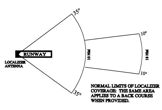
6. Unreliable signals may be received outside these areas.
c. Localizer Type Directional Aid (LDA)
1. The LDA is of comparable use and accuracy to a localizer but is not part of a complete ILS. The LDA course usually provides a more precise approach course than the similar Simplified Directional Facility (SDF) installation, which may have a course width of 6 or 12 degrees.
2. The LDA is not aligned with the runway. Straight-in minimums may be published where alignment does not exceed 30 degrees between the course and runway. Circling minimums only are published where this alignment exceeds 30 degrees.
3. A very
limited number of LDA approaches also incorporate a
glideslope. These are annotated in the plan view of the
instrument approach chart with a note, "LDA/Glideslope."
These procedures fall under a newly defined category of
approaches called Approach with Vertical Guidance (APV)
described in paragraph
5-4-5,
Instrument Approach Procedure Charts, subparagraph
a7(b),
Approach with Vertical Guidance (APV). LDA minima for with
and without glideslope is provided and annotated on the
minima lines of the approach chart as S-LDA/GS and S-LDA.
Because the final approach course is not aligned with the
runway centerline, additional maneuvering will be required
compared to an ILS approach.
d. Glide Slope/Glide Path
1. The UHF glide slope transmitter, operating on one of the 40 ILS channels within the frequency range 329.15 MHz, to 335.00 MHz radiates its signals in the direction of the localizer front course. The term "glide path" means that portion of the glide slope that intersects the localizer.
CAUTION-
False glide slope signals may exist in the area of the
localizer back course approach which can cause the glide
slope flag alarm to disappear and present unreliable glide
slope information. Disregard all glide slope signal
indications when making a localizer back course approach
unless a glide slope is specified on the approach and
landing chart.
2. The glide slope transmitter is located between 750 feet and 1,250 feet from the approach end of the runway (down the runway) and offset 250 to 650 feet from the runway centerline. It transmits a glide path beam 1.4 degrees wide (vertically). The signal provides descent information for navigation down to the lowest authorized decision height (DH) specified in the approved ILS approach procedure. The glidepath may not be suitable for navigation below the lowest authorized DH and any reference to glidepath indications below that height must be supplemented by visual reference to the runway environment. Glidepaths with no published DH are usable to runway threshold.
3. The glide path projection angle is normally adjusted to 3 degrees above horizontal so that it intersects the MM at about 200 feet and the OM at about 1,400 feet above the runway elevation. The glide slope is normally usable to the distance of 10 NM. However, at some locations, the glide slope has been certified for an extended service volume which exceeds 10 NM.
4. Pilots must be alert when approaching the glidepath interception. False courses and reverse sensing will occur at angles considerably greater than the published path.
5. Make every effort to remain on the indicated glide path.
CAUTION-
Avoid flying below the glide path to assure obstacle/terrain
clearance is maintained.
6. The published glide slope threshold crossing height (TCH) DOES NOT represent the height of the actual glide path on-course indication above the runway threshold. It is used as a reference for planning purposes which represents the height above the runway threshold that an aircraft's glide slope antenna should be, if that aircraft remains on a trajectory formed by the four-mile-to-middle marker glidepath segment.
7. Pilots must be aware of the vertical height between the aircraft's glide slope antenna and the main gear in the landing configuration and, at the DH, plan to adjust the descent angle accordingly if the published TCH indicates the wheel crossing height over the runway threshold may not be satisfactory. Tests indicate a comfortable wheel crossing height is approximately 20 to 30 feet, depending on the type of aircraft.
NOTE-
The TCH for a runway is established based on several factors
including the largest aircraft category that normally uses
the runway, how airport layout effects the glide slope
antenna placement, and terrain. A higher than optimum TCH,
with the same glide path angle, may cause the aircraft to
touch down further from the threshold if the trajectory of
the approach is maintained until the flare. Pilots should
consider the effect of a high TCH on the runway available
for stopping the aircraft.
e. Distance Measuring Equipment (DME)
1. When installed with the ILS and specified in the approach procedure, DME may be used:
(a) In lieu of the OM;
(b) As a back course (BC) final approach fix (FAF); and
(c) To establish other fixes on the localizer course.
2. In some cases, DME from a separate facility may be used within Terminal Instrument Procedures (TERPS) limitations:
(a) To provide ARC initial approach segments;
(b) As a FAF for BC approaches; and
(c) As a substitute for the OM.
f. Marker Beacon
1. ILS marker beacons have a rated power output of 3 watts or less and an antenna array designed to produce an elliptical pattern with dimensions, at 1,000 feet above the antenna, of approximately 2,400 feet in width and 4,200 feet in length. Airborne marker beacon receivers with a selective sensitivity feature should always be operated in the "low" sensitivity position for proper reception of ILS marker beacons.
2. Ordinarily, there are two marker beacons associated with an ILS, the OM and MM. Locations with a Category II ILS also have an Inner Marker (IM). When an aircraft passes over a marker, the pilot will receive the indications shown in TBL 1-1-3.
(a) The OM normally indicates a position at which an aircraft at the appropriate altitude on the localizer course will intercept the ILS glide path.
(b) The MM indicates a position approximately 3,500 feet from the landing threshold. This is also the position where an aircraft on the glide path will be at an altitude of approximately 200 feet above the elevation of the touchdown zone.
(c) The IM will indicate a point at which an aircraft is at a designated decision height (DH) on the glide path between the MM and landing threshold.
Marker Passage Indications
|
|
|
|
|
|
|
|
|
|
|
|
|
|
|
|
|
|
|
|
3. A back course marker normally indicates the ILS back course final approach fix where approach descent is commenced.
g. Compass Locator
1. Compass locator transmitters are often situated at the MM and OM sites. The transmitters have a power of less than 25 watts, a range of at least 15 miles and operate between 190 and 535 kHz. At some locations, higher powered radio beacons, up to 400 watts, are used as OM compass locators. These generally carry Transcribed Weather Broadcast (TWEB) information.
2. Compass locators transmit two letter identification groups. The outer locator transmits the first two letters of the localizer identification group, and the middle locator transmits the last two letters of the localizer identification group.
h. ILS Frequency (See TBL 1-1-4.)
Frequency Pairs Allocated for ILS
|
|
|
|
|
|
|
|
|
|
|
|
|
|
|
|
|
|
|
|
|
|
|
|
|
|
|
|
|
|
|
|
|
|
|
|
|
|
|
|
|
|
|
|
|
|
|
|
|
|
|
|
|
|
|
|
|
|
|
|
|
|
|
|
|
|
|
|
|
|
|
|
|
|
|
|
|
|
|
|
|
|
|
|
|
|
|
|
|
|
|
|
|
|
|
|
|
|
|
|
|
|
|
|
|
|
|
|
|
|
|
|
|
|
|
|
|
|
|
|
|
|
|
i. ILS Minimums
1. The lowest authorized ILS minimums, with all required ground and airborne systems components operative, are:
(a) Category I. Decision Height (DH) 200 feet and Runway Visual Range (RVR) 2,400 feet (with touchdown zone and centerline lighting, RVR 1,800 feet);
(b) Category II. DH 100 feet and RVR 1,200 feet;
(c) Category IIIa. No DH or DH below 100 feet and RVR not less than 700 feet;
(d) Category IIIb. No DH or DH below 50 feet and RVR less than 700 feet but not less than 150 feet; and
(e) Category IIIc. No DH and no RVR limitation.
NOTE-
Special authorization and equipment required for Categories
II and III.
j. Inoperative ILS Components
1. Inoperative localizer. When the localizer fails, an ILS approach is not authorized.
2. Inoperative glide slope. When the glide slope fails, the ILS reverts to a nonprecision localizer approach.
REFERENCE-
See the inoperative component table in the U.S. Government
Terminal Procedures Publication (TPP), for adjustments to
minimums due to inoperative airborne or ground system
equipment.
k. ILS Course Distortion
1. All pilots should be aware that disturbances to ILS localizer and glide slope courses may occur when surface vehicles or aircraft are operated near the localizer or glide slope antennas. Most ILS installations are subject to signal interference by either surface vehicles, aircraft or both. ILS CRITICAL AREAS are established near each localizer and glide slope antenna.
2. ATC issues control instructions to avoid interfering operations within ILS critical areas at controlled airports during the hours the Airport Traffic Control Tower (ATCT) is in operation as follows:
(a) Weather Conditions. Less than ceiling 800 feet and/or visibility 2 miles.
(1) Localizer Critical Area. Except for aircraft that land, exit a runway, depart or miss approach, vehicles and aircraft are not authorized in or over the critical area when an arriving aircraft is between the ILS final approach fix and the airport. Additionally, when the ceiling is less than 200 feet and/or the visibility is RVR 2,000 or less, vehicle and aircraft operations in or over the area are not authorized when an arriving aircraft is inside the ILS MM.
(2) Glide Slope Critical Area. Vehicles and aircraft are not authorized in the area when an arriving aircraft is between the ILS final approach fix and the airport unless the aircraft has reported the airport in sight and is circling or side stepping to land on a runway other than the ILS runway.
(b) Weather Conditions. At or above ceiling 800 feet and/or visibility 2 miles.
(1) No critical area protective action is provided under these conditions.
(2) A flight crew, under these conditions, should advise the tower that it will conduct an AUTOLAND or COUPLED approach to ensure that the ILS critical areas are protected when the aircraft is inside the ILS MM.
EXAMPLE-
Glide slope signal not protected.
3. Aircraft holding below 5,000 feet between the outer marker and the airport may cause localizer signal variations for aircraft conducting the ILS approach. Accordingly, such holding is not authorized when weather or visibility conditions are less than ceiling 800 feet and/or visibility 2 miles.
4. Pilots are
cautioned that vehicular traffic not subject to ATC may
cause momentary deviation to ILS course or glide slope
signals. Also, critical areas are not protected at
uncontrolled airports or at airports with an operating
control tower when weather or visibility conditions are
above those requiring protective measures. Aircraft
conducting coupled or autoland operations should be
especially alert in monitoring automatic flight control
systems.
(See FIG
1-1-7.)
NOTE-
Unless otherwise coordinated through Flight Standards, ILS
signals to Category I runways are not flight inspected below
100 feet AGL. Guidance signal anomalies may be encountered
below this altitude.
1-1-10. Simplified Directional Facility (SDF)
a. The SDF provides a final approach course similar to that of the ILS localizer. It does not provide glide slope information. A clear understanding of the ILS localizer and the additional factors listed below completely describe the operational characteristics and use of the SDF.
b. The SDF transmits signals within the range of 108.10 to 111.95 MHz.
c. The approach techniques and procedures used in an SDF instrument approach are essentially the same as those employed in executing a standard localizer approach except the SDF course may not be aligned with the runway and the course may be wider, resulting in less precision.
d. Usable off-course indications are limited to 35 degrees either side of the course centerline. Instrument indications received beyond 35 degrees should be disregarded.
e. The SDF antenna may be offset from the runway centerline. Because of this, the angle of convergence between the final approach course and the runway bearing should be determined by reference to the instrument approach procedure chart. This angle is generally not more than 3 degrees. However, it should be noted that inasmuch as the approach course originates at the antenna site, an approach which is continued beyond the runway threshold will lead the aircraft to the SDF offset position rather than along the runway centerline.
FIG
1-1-7
FAA Instrument Landing Systems
FAA Instrument Landing Systems
f. The SDF signal is fixed at either 6 degrees or 12 degrees as necessary to provide maximum flyability and optimum course quality.
g. Identification consists of a three-letter identifier transmitted in Morse Code on the SDF frequency. The appropriate instrument approach chart will indicate the identifier used at a particular airport.
1-1-11. Microwave Landing System (MLS)
a. General
1. The MLS provides precision navigation guidance for exact alignment and descent of aircraft on approach to a runway. It provides azimuth, elevation, and distance.
2. Both lateral and vertical guidance may be displayed on conventional course deviation indicators or incorporated into multipurpose cockpit displays. Range information can be displayed by conventional DME indicators and also incorporated into multipurpose displays.
3. The MLS supplements the ILS as the standard landing system in the U.S. for civil, military, and international civil aviation. At international airports, ILS service is protected to 2010.
4. The system may be divided into five functions:
(b) Back azimuth;
5. The standard configuration of MLS ground equipment includes:
(a) An azimuth station to perform functions (a) and (e) above. In addition to providing azimuth navigation guidance, the station transmits basic data which consists of information associated directly with the operation of the landing system, as well as advisory data on the performance of the ground equipment.
(b) An elevation station to perform function (c).
(c) Distance Measuring Equipment (DME) to perform range guidance, both standard DME (DME/N) and precision DME (DME/P).
6. MLS Expansion Capabilities. The standard configuration can be expanded by adding one or more of the following functions or characteristics.
(a) Back azimuth. Provides lateral guidance for missed approach and departure navigation.
(b) Auxiliary data transmissions. Provides additional data, including refined airborne positioning, meteorological information, runway status, and other supplementary information.
(c) Expanded Service Volume (ESV) proportional guidance to 60 degrees.
7. MLS identification is a four-letter designation starting with the letter M. It is transmitted in International Morse Code at least six times per minute by the approach azimuth (and back azimuth) ground equipment.
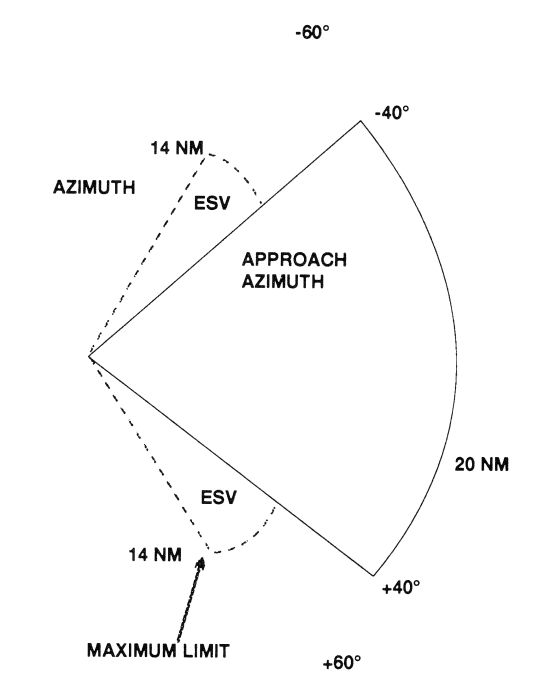
b. Approach Azimuth Guidance
1. The azimuth station transmits MLS angle and data on one of 200 channels within the frequency range of 5031 to 5091 MHz.
2. The equipment is normally located about 1,000 feet beyond the stop end of the runway, but there is considerable flexibility in selecting sites. For example, for heliport operations the azimuth transmitter can be collocated with the elevation transmitter.
3. The azimuth
coverage extends:
(See FIG
1-1-8.)
(a) Laterally, at least 40 degrees on either side of the runway centerline in a standard configuration,
(b) In elevation, up to an angle of 15 degrees and to at least 20,000 feet, and
(c) In range, to at least 20 NM.
FIG
1-1-8
Coverage Volume
Azimuth
Coverage Volume
Azimuth
c. Elevation Guidance
1. The elevation station transmits signals on the same frequency as the azimuth station. A single frequency is time-shared between angle and data functions.
2. The elevation transmitter is normally located about 400 feet from the side of the runway between runway threshold and the touchdown zone.
3. Elevation coverage is provided in the same airspace as the azimuth guidance signals:
(a) In elevation, to at least +15 degrees;
(b) Laterally, to fill the Azimuth lateral coverage; and
(c) In range,
to at least 20 NM.
(See FIG
1-1-9.)
FIG
1-1-9
Coverage Volumes
Elevation
Coverage Volumes
Elevation
d. Range Guidance
1. The MLS Precision Distance Measuring Equipment (DME/P) functions the same as the navigation DME described in paragraph 1-1-7, Distance Measuring Equipment (DME), but there are some technical differences. The beacon transponder operates in the frequency band 962 to 1105 MHz and responds to an aircraft interrogator. The MLS DME/P accuracy is improved to be consistent with the accuracy provided by the MLS azimuth and elevation stations.
2. A DME/P channel is paired with the azimuth and elevation channel. A complete listing of the 200 paired channels of the DME/P with the angle functions is contained in FAA Standard 022 (MLS Interoperability and Performance Requirements).
3. The DME/N or DME/P is an integral part of the MLS and is installed at all MLS facilities unless a waiver is obtained. This occurs infrequently and only at outlying, low density airports where marker beacons or compass locators are already in place.
e. Data Communications
1. The data transmission can include both the basic and auxiliary data words. All MLS facilities transmit basic data. Where needed, auxiliary data can be transmitted.
2. Coverage limits. MLS data are transmitted throughout the azimuth (and back azimuth when provided) coverage sectors.
3. Basic data content. Representative data include:
(a) Station identification;
(b) Exact locations of azimuth, elevation and DME/P stations (for MLS receiver processing functions);
(c) Ground equipment performance level; and
(d) DME/P channel and status.
4. Auxiliary data content: Representative data include:
(a) 3-D locations of MLS equipment;
(b) Waypoint coordinates;
(c) Runway conditions; and
(d) Weather (e.g., RVR, ceiling, altimeter setting, wind, wake vortex, wind shear).
f. Operational Flexibility
1. The MLS has the capability to fulfill a variety of needs in the approach, landing, missed approach and departure phases of flight. For example:
(a) Curved and segmented approaches;
(b) Selectable glide path angles;
(c) Accurate 3-D positioning of the aircraft in space; and
(d) The establishment of boundaries to ensure clearance from obstructions in the terminal area.
2. While many of these capabilities are available to any MLS-equipped aircraft, the more sophisticated capabilities (such as curved and segmented approaches) are dependent upon the particular capabilities of the airborne equipment.
g. Summary
1. Accuracy. The MLS provides precision three-dimensional navigation guidance accurate enough for all approach and landing maneuvers.
2. Coverage.
Accuracy is consistent throughout the coverage
volumes.
(See FIG
1-1-10.)
FIG
1-1-10
Coverage Volumes
3-D Representation
Coverage Volumes
3-D Representation
3. Environment. The system has low susceptibility to interference from weather conditions and airport ground traffic.
4. Channels. MLS has 200 channels- enough for any foreseeable need.
5. Data. The MLS transmits ground-air data messages associated with the systems operation.
6. Range information. Continuous range information is provided with an accuracy of about 100 feet.
1-1-12. NAVAID Identifier Removal During Maintenance
During periods of routine or emergency maintenance, coded identification (or code and voice, where applicable) is removed from certain FAA NAVAIDs. Removal of identification serves as a warning to pilots that the facility is officially off the air for tune-up or repair and may be unreliable even though intermittent or constant signals are received.
NOTE-
During periods of maintenance VHF ranges may radiate a
T-E-S-T code (- D DDD -).
NOTE-
DO NOT attempt to fly a procedure that is NOTAMed out of
service even if the identification is present. In certain
cases, the identification may be transmitted for short
periods as part of the testing.
a. Voice equipped en route radio navigational aids are under the operational control of either an FAA Automated Flight Service Station (AFSS) or an approach control facility. The voice communication is available on some facilities. Hazardous Inflight Weather Advisory Service (HIWAS) broadcast capability is available on selected VOR sites throughout the conterminous U.S. and does not provide two-way voice communication. The availability of two-way voice communication and HIWAS is indicated in the A/FD and aeronautical charts.
b. Unless otherwise noted on the chart, all radio navigation aids operate continuously except during shutdowns for maintenance. Hours of operation of facilities not operating continuously are annotated on charts and in the A/FD.
1-1-14. User Reports on NAVAID Performance
a. Users of the National Airspace System (NAS) can render valuable assistance in the early correction of NAVAID malfunctions by reporting their observations of undesirable NAVAID performance. Although NAVAIDs are monitored by electronic detectors, adverse effects of electronic interference, new obstructions or changes in terrain near the NAVAID can exist without detection by the ground monitors. Some of the characteristics of malfunction or deteriorating performance which should be reported are: erratic course or bearing indications; intermittent, or full, flag alarm; garbled, missing or obviously improper coded identification; poor quality communications reception; or, in the case of frequency interference, an audible hum or tone accompanying radio communications or NAVAID identification.
b. Reporters should identify the NAVAID, location of the aircraft, time of the observation, type of aircraft and describe the condition observed; the type of receivers in use is also useful information. Reports can be made in any of the following ways:
1. Immediate report by direct radio communication to the controlling Air Route Traffic Control Center (ARTCC), Control Tower, or FSS. This method provides the quickest result.
2. By telephone to the nearest FAA facility.
3. By FAA Form 8000-7, Safety Improvement Report, a postage-paid card designed for this purpose. These cards may be obtained at FAA FSSs, Flight Standards District Offices, and General Aviation Fixed Base Operations.
c. In aircraft that have more than one receiver, there are many combinations of possible interference between units. This can cause either erroneous navigation indications or, complete or partial blanking out of the communications. Pilots should be familiar enough with the radio installation of the particular airplanes they fly to recognize this type of interference.
a. Introduction
1. The LOng RAnge Navigation-C (LORAN) system is a hyperbolic, terrestrial-based navigation system operating in the 90-110 kHz frequency band. LORAN, operated by the U.S. Coast Guard (USCG), has been in service for over 50 years and is used for navigation by the various transportation modes, as well as, for precise time and frequency applications. The system is configured to provide reliable, all weather navigation for marine users along the U.S. coasts and in the Great Lakes.
2. In the 1980's, responding to aviation user and industry requests, the USCG and FAA expanded LORAN coverage to include the entire continental U.S. This work was completed in late 1990, but the LORAN system failed to gain significant user acceptance and primarily due to transmitter and user equipment performance limitations, attempts to obtain FAA certification of nonprecision approach capable receivers were unsuccessful. More recently, concern regarding the vulnerability of Global Positioning System (GPS) and the consequences of losing GPS on the critical U.S. infrastructure (e.g., NAS) has renewed and refocused attention on LORAN.
3. LORAN is also supported in the Canadian airspace system. Currently, LORAN receivers are only certified for en route navigation.
4. Additional information can be found in the "LORAN-C User Handbook," COMDT PUB-P16562.6, or the website http://www.navcen.uscg.gov.
b. LORAN Chain
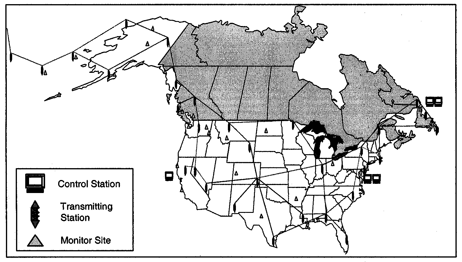
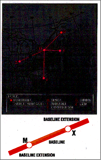
1. The
locations of the U.S. and Canadian LORAN transmitters and
monitor sites are illustrated in FIG
1-1-11. Station operations are
organized into subgroups of four to six stations called
"chains." One station in the chain is designated the
"Master" and the others are "secondary" stations. The
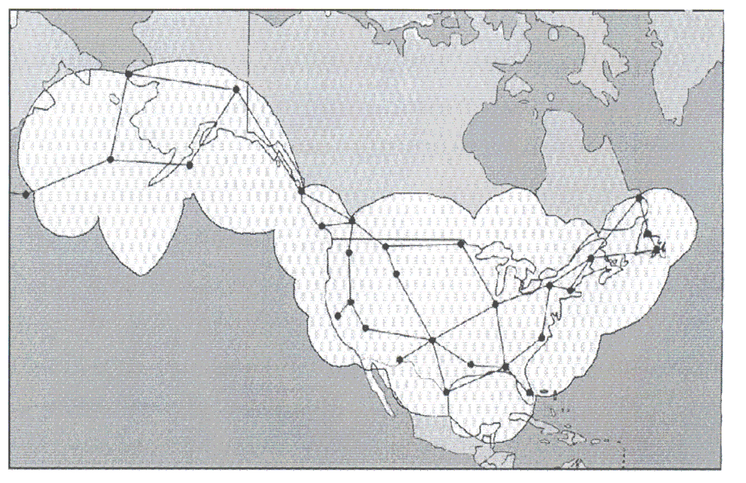
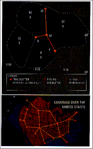
resulting chain based coverage is seen in
FIG
1-1-12.
FIG
1-1-11
U.S. and Canadian LORAN System
Architecture
U.S. and Canadian LORAN System Architecture
FIG
1-1-12
LORAN Chain Based Coverage
LORAN Chain Based Coverage
2.
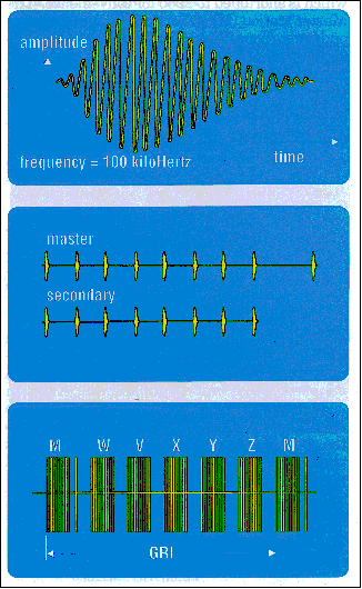
The LORAN navigation signal is a carefully structured
sequence of brief radio frequency pulses centered at 100
kHz. The sequence of signal transmissions consists of a
pulse group from the Master (M) station followed at precise
time intervals by groups from the secondary stations, which
are designated by the U.S. Coast Guard with the letters V,
W, X, Y and Z. All secondary stations radiate pulses in
groups of eight, but for identification the Master signal
has an additional ninth pulse. (See
FIG
1-1-13.) The timing of the
LORAN system is tightly controlled and synchronized to
Coordinated Universal Time (UTC). Like the GPS, this is a
Stratum 1 timing standard.
3. The time interval between the reoccurrence of the Master pulse group is called the Group Repetition Interval (GRI). The GRI is the same for all stations in a chain and each LORAN chain has a unique GRI. Since all stations in a particular chain operate on the same radio frequency, the GRI is the key by which a LORAN receiver can identify and isolate signal groups from a specific chain.
EXAMPLE-
Transmitters in the Northeast U.S. chain
(FIG
1-1-14)
operate with a GRI of 99,600 microseconds which
is shortened to 9960 for convenience. The master station (M)
at Seneca, New York, controls secondary stations (W) at
Caribou, Maine; (X) at Nantucket, Massachusetts; (Y) at
Carolina Beach, North Carolina, and (Z) at Dana, Indiana. In
order to keep chain operations precise, monitor receivers
are located at Cape Elizabeth, ME; Sandy Hook, NJ; Dunbar
Forest, MI, and Plumbrook, OH. Monitor receivers
continuously measure various aspects of the quality (e.g.,
pulse shape) and accuracy (e.g., timing) of LORAN signals
and report system status to a control station.
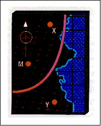
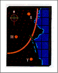
4. The line between the Master and each secondary station is the "baseline" for a pair of stations. Typical baselines are from 600 to 1,000 nautical miles in length. The continuation of the baseline in either direction is a "baseline extension."
5. At the LORAN transmitter stations there are cesium oscillators, transmitter time and control equipment, a transmitter, primary power (e.g., commercial or generator) and auxiliary power equipment (e.g., uninterruptible power supplies and generators), and a transmitting antenna (configurations may either have 1 or 4 towers) with the tower heights ranging from 700 to 1350 feet tall. Depending on the coverage area requirements a LORAN station transmits from 400 to 1,600 kilowatts of peak signal power.
6. The USCG operates the LORAN transmitter stations under a reduced staffing structure that is made possible by the remote control and monitoring of the critical station and signal parameters. The actual control of the transmitting station is accomplished remotely at Coast Guard Navigation Center (NAVCEN) located in Alexandria, Virginia. East Coast and Midwest stations are controlled by the NAVCEN. Stations on the West Coast and in Alaska are controlled by the NAVCEN Detachment (Det), located in Petaluma, California. In the event of a problem at one of these two 24 hour-a-day staffed sites, monitoring and control of the entire LORAN system can be done at either location. If both NACEN and NAVCEN Det are down or if there is an equipment problem at a specific station, local station personnel are available to operate and perform repairs at each LORAN station.
7. The transmitted signal is also monitored in the service areas (i.e., area of published LORAN coverage) and its status provided to NAVCEN and NAVCEN Det. The System Area Monitor (SAM) is a single site used to observe the transmitted signal (signal strength, time difference, and pulse shape). If an out-of-tolerance situation that could affect navigation accuracy is detected, an alert signal called "Blink" is activated. Blink is a distinctive change in the group of eight pulses that can be recognized automatically by a receiver so the user is notified instantly that the LORAN system should not be used for navigation. Out-of-tolerance situations which only the local station can detect are also monitored. These situations when detected cause signal transmissions from a station to be halted.
8. Each individual LORAN chain provides navigation-quality signal coverage over an identified area as shown in FIG 1-1-15 for the West Coast chain, GRI 9940. The chain Master station is at Fallon, Nevada, and secondary stations are at George, Washington; Middletown, California, and Searchlight, Nevada. In a signal coverage area the signal strength relative to the normal ambient radio noise must be adequate to assure successful reception. Similar coverage area charts are available for all chains.
FIG
1-1-13
The LORAN Pulse and Pulse Group
The LORAN Pulse and Pulse Group
FIG
1-1-14
Northeast U.S. LORAN Chain
Northeast U.S. LORAN Chain
FIG
1-1-15
West Coast U.S. LORAN Chain
West Coast U.S. LORAN Chain
c. The LORAN Receiver
1. For a currently certified LORAN aviation receiver to provide navigation information for a pilot, it must successfully receive, or "acquire," signals from three or more stations in a chain. Acquisition involves the time synchronization of the receiver with the chain GRI, identification of the Master station signals from among those checked, identification of secondary station signals, and the proper selection of the tracking point on each signal at which measurements are made. However, a new generation of receivers has been developed that use pulses from all stations that can be received at the pilot's location. Use of "all-in-view" stations by a receiver is made possible due to the synchronization of LORAN stations signals to UTC. This new generation of receivers, along with improvements at the transmitting stations and changes in system policy and operations doctrine may allow for LORAN's use in nonprecision approaches. At this time these receivers are available for purchase, but none have been certified for aviation use.
2. The basic measurements made by certified LORAN receivers are the differences in time-of-arrival between the Master signal and the signals from each of the secondary stations of a chain. Each "time difference" (TD) value is measured to a precision of about 0.1 microseconds. As a rule of thumb, 0.1 microsecond is equal to about 100 feet.
3. An aircraft's LORAN receiver must recognize three signal conditions:
(a) Usable signals;
(b) Absence of signals, and
(c) Signal blink.
4. The most critical phase of flight is during the approach to landing at an airport. During the approach phase the receiver must detect a lost signal, or a signal Blink, within 10 seconds of the occurrence and warn the pilot of the event. At this time there are no receivers that are certified for nonprecision approaches.
5. Most certified receivers have various internal tests for estimating the probable accuracy of the current TD values and consequent navigation solutions. Tests may include verification of the timing alignment of the receiver clock with the LORAN pulse, or a continuous measurement of the signal-to-noise ratio (SNR). SNR is the relative strength of the LORAN signals compared to the local ambient noise level. If any of the tests fail, or if the quantities measured are out of the limits set for reliable navigation, then an alarm will be activated to alert the pilot.
6. LORAN signals operate in the low frequency band (90-110 kHz) that has been reserved for marine navigation signals. Adjacent to the band, however, are numerous low frequency communications transmitters. Nearby signals can distort the LORAN signals and must be eliminated by the receiver to assure proper operation. To eliminate interfering signals, LORAN receivers have selective internal filters. These filters, commonly known as "notch filters," reduce the effect of interfering signals.
7. Careful installation of antennas, good metal-to-metal electrical bonding, and provisions for precipitation noise discharge on the aircraft are essential for the successful operation of LORAN receivers. A LORAN antenna should be installed on an aircraft in accordance with the manufacturer's instructions. Corroded bonding straps should be replaced, and static discharge devices installed at points indicated by the aircraft manufacturer.
d. LORAN Navigation
1. An airborne LORAN receiver has four major parts:
(a) Signal processor;
(b) Navigation computer;
(c) Control/display, and
(d) Antenna.
2. The signal processor acquires LORAN signals and measures the difference between the time-of-arrival of each secondary station pulse group and the Master station pulse group. The measured TDs depend on the location of the receiver in relation to the three or more transmitters.
FIG
1-1-16
First Line-of-Position
First Line-of-Position
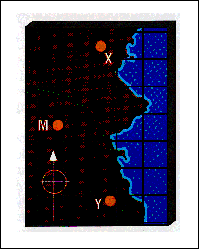
(a) The first TD will locate an aircraft somewhere on a line-of-position (LOP) on which the receiver will measure the same TD value.
(b) A second LOP is defined by a TD measurement between the Master station signal and the signal from another secondary station.
FIG
1-1-17
Second Line-of-Position
Second Line-of-Position
(c) The intersection of the measured LOPs is the position of the aircraft.
FIG
1-1-18
Intersection of Lines-of-Position
Intersection of Lines-of-Position
3. The navigation computer converts TD values to corresponding latitude and longitude. Once the time and position of the aircraft are established at two points, distance to destination, cross track error, ground speed, estimated time of arrival, etc., can be determined. Cross track error can be displayed as the vertical needle of a course deviation indicator, or digitally, as decimal parts of a mile left or right of course.
e. Notices to Airmen (NOTAMs) are issued for LORAN chain or station outages. Domestic NOTAM (D)s are issued under the identifier "LRN." International NOTAMs are issued under the KNMH series. Pilots may obtain these NOTAMs from FSS briefers upon request.
f. LORAN status information. To find out more information on the LORAN system and its operational status you can visit http://www.navcen.uscg.gov/loran/default.htm or contact NAVCEN's Navigation Information Service (NIS) watchstander, phone (703) 313-5900, fax (703) 313-5920.
g. LORAN's future. The U.S. will continue to operate the LORAN system in the short term. During this time, the FAA LORAN evaluation program, being conducted with the support of a team comprising government, academia, and industry, will identify and assess LORAN's potential contributions to required navigation services for the National Airspace System (NAS), and support decisions regarding continued operation of the system. If the government concludes LORAN should not be kept as part of the mix of federally provided radio navigation systems, it will give the users of LORAN reasonable notice so that they will have the opportunity to transition to alternative navigation aids.
a. The VHF Direction Finder (VHF/DF) is one of the common systems that helps pilots without their being aware of its operation. It is a ground-based radio receiver used by the operator of the ground station. FAA facilities that provide VHF/DF service are identified in the A/FD.
b. The equipment consists of a directional antenna system and a VHF radio receiver.
c. The VHF/DF receiver display indicates the magnetic direction of the aircraft from the ground station each time the aircraft transmits.
d. DF equipment is of particular value in locating lost aircraft and in helping to identify aircraft on radar.
REFERENCE-
AIM, Direction Finding Instrument Approach Procedure,
Paragraph 6-2-3.
1-1-17. Inertial Reference Unit (IRU), Inertial Navigation System (INS), and Attitude Heading Reference System (AHRS)
a. IRUs are self-contained systems comprised of gyros and accelerometers that provide aircraft attitude (pitch, roll, and heading), position, and velocity information in response to signals resulting from inertial effects on system components. Once aligned with a known position, IRUs continuously calculate position and velocity. IRU position accuracy decays with time. This degradation is known as "drift."
b. INSs combine the components of an IRU with an internal navigation computer. By programming a series of waypoints, these systems will navigate along a predetermined track.
c. AHRSs are electronic devices that provide attitude information to aircraft systems such as weather radar and autopilot, but do not directly compute position information.
Doppler Radar is a semiautomatic self-contained dead reckoning navigation system (radar sensor plus computer) which is not continuously dependent on information derived from ground based or external aids. The system employs radar signals to detect and measure ground speed and drift angle, using the aircraft compass system as its directional reference. Doppler is less accurate than INS, however, and the use of an external reference is required for periodic updates if acceptable position accuracy is to be achieved on long range flights.
1-1-19. Global Positioning System (GPS)
1. System Description. The Global Positioning System is a satellite-based radio navigation system, which broadcasts a signal that is used by receivers to determine precise position anywhere in the world. The receiver tracks multiple satellites and determines a pseudorange measurement that is then used to determine the user location. A minimum of four satellites is necessary to establish an accurate three-dimensional position. The Department of Defense (DOD) is responsible for operating the GPS satellite constellation and monitors the GPS satellites to ensure proper operation. Every satellite's orbital parameters (ephemeris data) are sent to each satellite for broadcast as part of the data message embedded in the GPS signal. The GPS coordinate system is the Cartesian earth-centered earth-fixed coordinates as specified in the World Geodetic System 1984 (WGS-84).
2. System Availability and Reliability
(a) The status of GPS satellites is broadcast as part of the data message transmitted by the GPS satellites. GPS status information is also available by means of the U.S. Coast Guard navigation information service: (703) 313-5907, Internet: http://www.navcen.uscg.gov/. Additionally, satellite status is available through the Notice to Airmen (NOTAM) system.
(b) The operational status of GNSS operations depends upon the type of equipment being used. For GPS-only equipment TSO-C129(a), the operational status of nonprecision approach capability for flight planning purposes is provided through a prediction program that is embedded in the receiver or provided separately.
3. Receiver Autonomous Integrity Monitoring (RAIM). When GNSS equipment is not using integrity information from WAAS or LAAS, the GPS navigation receiver using RAIM provides GPS signal integrity monitoring. RAIM is necessary since delays of up to two hours can occur before an erroneous satellite transmission can be detected and corrected by the satellite control segment. The RAIM function is also referred to as fault detection. Another capability, fault exclusion, refers to the ability of the receiver to exclude a failed satellite from the position solution and is provided by some GPS receivers and by WAAS receivers.
4. The GPS receiver verifies the integrity (usability) of the signals received from the GPS constellation through receiver autonomous integrity monitoring (RAIM) to determine if a satellite is providing corrupted information. At least one satellite, in addition to those required for navigation, must be in view for the receiver to perform the RAIM function; thus, RAIM needs a minimum of 5 satellites in view, or 4 satellites and a barometric altimeter (baro-aiding) to detect an integrity anomaly. For receivers capable of doing so, RAIM needs 6 satellites in view (or 5 satellites with baro-aiding) to isolate the corrupt satellite signal and remove it from the navigation solution. Baro-aiding is a method of augmenting the GPS integrity solution by using a nonsatellite input source. GPS derived altitude should not be relied upon to determine aircraft altitude since the vertical error can be quite large and no integrity is provided. To ensure that baro-aiding is available, the current altimeter setting must be entered into the receiver as described in the operating manual.
5. RAIM messages vary somewhat between receivers; however, generally there are two types. One type indicates that there are not enough satellites available to provide RAIM integrity monitoring and another type indicates that the RAIM integrity monitor has detected a potential error that exceeds the limit for the current phase of flight. Without RAIM capability, the pilot has no assurance of the accuracy of the GPS position.
6. Selective Availability. Selective Availability (SA) is a method by which the accuracy of GPS is intentionally degraded. This feature is designed to deny hostile use of precise GPS positioning data. SA was discontinued on May 1, 2000, but many GPS receivers are designed to assume that SA is still active. New receivers may take advantage of the discontinuance of SA based on the performance values in ICAO Annex 10, and do not need to be designed to operate outside of that performance.
7. The GPS constellation of 24 satellites is designed so that a minimum of five is always observable by a user anywhere on earth. The receiver uses data from a minimum of four satellites above the mask angle (the lowest angle above the horizon at which it can use a satellite).
8. The DOD declared initial operational capability (IOC) of the U.S. GPS on December 8, 1993. The FAA has granted approval for U.S. civil operators to use properly certified GPS equipment as a primary means of navigation in oceanic airspace and certain remote areas. Properly certified GPS equipment may be used as a supplemental means of IFR navigation for domestic en route, terminal operations, and certain instrument approach procedures (IAPs). This approval permits the use of GPS in a manner that is consistent with current navigation requirements as well as approved air carrier operations specifications.
b. VFR Use of GPS
1. GPS navigation has become a great asset to VFR pilots, providing increased navigation capability and enhanced situational awareness, while reducing operating costs due to greater ease in flying direct routes. While GPS has many benefits to the VFR pilot, care must be exercised to ensure that system capabilities are not exceeded.
2. Types of receivers used for GPS navigation under VFR are varied, from a full IFR installation being used to support a VFR flight, to a VFR only installation (in either a VFR or IFR capable aircraft) to a hand-held receiver. The limitations of each type of receiver installation or use must be understood by the pilot to avoid misusing navigation information. (See TBL 1-1-6.) In all cases, VFR pilots should never rely solely on one system of navigation. GPS navigation must be integrated with other forms of electronic navigation (when possible), as well as pilotage and dead reckoning. Only through the integration of these techniques can the VFR pilot ensure accuracy in navigation.
3. Some critical concerns in VFR use of GPS include RAIM capability, database currency and antenna location.
(a) RAIM Capability. Many VFR GPS receivers and all hand-held units have no RAIM alerting capability. Loss of the required number of satellites in view, or the detection of a position error, cannot be displayed to the pilot by such receivers. In receivers with no RAIM capability, no alert would be provided to the pilot that the navigation solution had deteriorated, and an undetected navigation error could occur. A systematic cross-check with other navigation techniques would identify this failure, and prevent a serious deviation. See subparagraphs a4 and a5 for more information on RAIM.
(b) Database Currency
(1) In many receivers, an up-datable database is used for navigation fixes, airports, and instrument procedures. These databases must be maintained to the current update for IFR operation, but no such requirement exists for VFR use.
(2) However, in many cases, the database drives a moving map display which indicates Special Use Airspace and the various classes of airspace, in addition to other operational information. Without a current database the moving map display may be outdated and offer erroneous information to VFR pilots wishing to fly around critical airspace areas, such as a Restricted Area or a Class B airspace segment. Numerous pilots have ventured into airspace they were trying to avoid by using an outdated database. If you don't have a current database in the receiver, disregard the moving map display for critical navigation decisions.
(3) In addition, waypoints are added, removed, relocated, or re-named as required to meet operational needs. When using GPS to navigate relative to a named fix, a current database must be used to properly locate a named waypoint. Without the update, it is the pilot's responsibility to verify the waypoint location referencing to an official current source, such as the Airport/Facility Directory, Sectional Chart, or En Route Chart.
(c) Antenna Location
(1) In many VFR installations of GPS receivers, antenna location is more a matter of convenience than performance. In IFR installations, care is exercised to ensure that an adequate clear view is provided for the antenna to see satellites. If an alternate location is used, some portion of the aircraft may block the view of the antenna, causing a greater opportunity to lose navigation signal.
(2) This is especially true in the case of hand-helds. The use of hand-held receivers for VFR operations is a growing trend, especially among rental pilots. Typically, suction cups are used to place the GPS antennas on the inside of cockpit windows. While this method has great utility, the antenna location is limited to the cockpit or cabin only and is rarely optimized to provide a clear view of available satellites. Consequently, signal losses may occur in certain situations of aircraft-satellite geometry, causing a loss of navigation signal. These losses, coupled with a lack of RAIM capability, could present erroneous position and navigation information with no warning to the pilot.
(3) While the use of a hand-held GPS for VFR operations is not limited by regulation, modification of the aircraft, such as installing a panel- or yoke-mounted holder, is governed by 14 CFR Part 43. Consult with your mechanic to ensure compliance with the regulation, and a safe installation.
4. As a result of these and other concerns, here are some tips for using GPS for VFR operations:
(a) Always check to see if your unit has RAIM capability. If no RAIM capability exists, be suspicious of your GPS position when any disagreement exists with the position derived from other radio navigation systems, pilotage, or dead reckoning.
(b) Check the currency of the database, if any. If expired, update the database using the current revision. If an update of an expired database is not possible, disregard any moving map display of airspace for critical navigation decisions. Be aware that named waypoints may no longer exist or may have been relocated since the database expired. At a minimum, the waypoints planned to be used should be checked against a current official source, such as the Airport/Facility Directory, or a Sectional Aeronautical Chart.
(c) While hand-helds can provide excellent navigation capability to VFR pilots, be prepared for intermittent loss of navigation signal, possibly with no RAIM warning to the pilot. If mounting the receiver in the aircraft, be sure to comply with 14 CFR Part 43.
(d) Plan flights carefully before taking off. If you wish to navigate to user-defined waypoints, enter them before flight, not on-the-fly. Verify your planned flight against a current source, such as a current sectional chart. There have been cases in which one pilot used waypoints created by another pilot that were not where the pilot flying was expecting. This generally resulted in a navigation error. Minimize head-down time in the aircraft and keep a sharp lookout for traffic, terrain, and obstacles. Just a few minutes of preparation and planning on the ground will make a great difference in the air.
(e) Another way to minimize head-down time is to become very familiar with your receiver's operation. Most receivers are not intuitive. The pilot must take the time to learn the various keystrokes, knob functions, and displays that are used in the operation of the receiver. Some manufacturers provide computer-based tutorials or simulations of their receivers. Take the time to learn about your particular unit before you try to use it in flight.
5. In summary, be careful not to rely on GPS to solve all your VFR navigational problems. Unless an IFR receiver is installed in accordance with IFR requirements, no standard of accuracy or integrity has been assured. While the practicality of GPS is compelling, the fact remains that only the pilot can navigate the aircraft, and GPS is just one of the pilot's tools to do the job.
c. VFR Waypoints
1. VFR waypoints provide VFR pilots with a supplementary tool to assist with position awareness while navigating visually in aircraft equipped with area navigation receivers. VFR waypoints should be used as a tool to supplement current navigation procedures. The uses of VFR waypoints include providing navigational aids for pilots unfamiliar with an area, waypoint definition of existing reporting points, enhanced navigation in and around Class B and Class C airspace, and enhanced navigation around Special Use Airspace. VFR pilots should rely on appropriate and current aeronautical charts published specifically for visual navigation. If operating in a terminal area, pilots should take advantage of the Terminal Area Chart available for that area, if published. The use of VFR waypoints does not relieve the pilot of any responsibility to comply with the operational requirements of 14 CFR Part 91.
2. VFR waypoint names (for computer-entry and flight plans) consist of five letters beginning with the letters "VP" and are retrievable from navigation databases. The VFR waypoint names are not intended to be pronounceable, and they are not for use in ATC communications. On VFR charts, stand-alone VFR waypoints will be portrayed using the same four-point star symbol used for IFR waypoints. VFR waypoints collocated with visual check points on the chart will be identified by small magenta flag symbols. VFR waypoints collocated with visual check points will be pronounceable based on the name of the visual check point and may be used for ATC communications. Each VFR waypoint name will appear in parentheses adjacent to the geographic location on the chart. Latitude/longitude data for all established VFR waypoints may be found in the appropriate regional Airport/Facility Directory (A/FD).
3. VFR waypoints shall not be used to plan flights under IFR. VFR waypoints will not be recognized by the IFR system and will be rejected for IFR routing purposes.
4. When filing VFR flight plans, pilots may use the five letter identifier as a waypoint in the route of flight section if there is an intended course change at that point or if used to describe the planned route of flight. This VFR filing would be similar to how a VOR would be used in a route of flight. Pilots must use the VFR waypoints only when operating under VFR conditions.
5. Any VFR waypoints intended for use during a flight should be loaded into the receiver while on the ground and prior to departure. Once airborne, pilots should avoid programming routes or VFR waypoint chains into their receivers.
6. Pilots should be especially vigilant for other traffic while operating near VFR waypoints. The same effort to see and avoid other aircraft near VFR waypoints will be necessary, as was the case with VORs and NDBs in the past. In fact, the increased accuracy of navigation through the use of GPS will demand even greater vigilance, as off-course deviations among different pilots and receivers will be less. When operating near a VFR waypoint, use whatever ATC services are available, even if outside a class of airspace where communications are required. Regardless of the class of airspace, monitor the available ATC frequency closely for information on other aircraft operating in the vicinity. It is also a good idea to turn on your landing light(s) when operating near a VFR waypoint to make your aircraft more conspicuous to other pilots, especially when visibility is reduced. See paragraph 7-5-2, VFR in Congested Areas, for more information.
d. General Requirements
1. Authorization to conduct any GPS operation under IFR requires that:
(a) GPS navigation equipment used must be approved in accordance with the requirements specified in Technical Standard Order (TSO) TSO-C129, or equivalent, and the installation must be done in accordance with Advisory Circular AC 20-138, Airworthiness Approval of Global Positioning System (GPS) Navigation Equipment for Use as a VFR and IFR Supplemental Navigation System, or Advisory Circular AC 20-130A, Airworthiness Approval of Navigation or Flight Management Systems Integrating Multiple Navigation Sensors, or equivalent. Equipment approved in accordance with TSO-C115a does not meet the requirements of TSO-C129. Visual flight rules (VFR) and hand-held GPS systems are not authorized for IFR navigation, instrument approaches, or as a principal instrument flight reference. During IFR operations they may be considered only an aid to situational awareness.
(b) Aircraft using GPS navigation equipment under IFR must be equipped with an approved and operational alternate means of navigation appropriate to the flight. Active monitoring of alternative navigation equipment is not required if the GPS receiver uses RAIM for integrity monitoring. Active monitoring of an alternate means of navigation is required when the RAIM capability of the GPS equipment is lost.
(c) Procedures must be established for use in the event that the loss of RAIM capability is predicted to occur. In situations where this is encountered, the flight must rely on other approved equipment, delay departure, or cancel the flight.
(d) The GPS operation must be conducted in accordance with the FAA-approved aircraft flight manual (AFM) or flight manual supplement. Flight crew members must be thoroughly familiar with the particular GPS equipment installed in the aircraft, the receiver operation manual, and the AFM or flight manual supplement. Unlike ILS and VOR, the basic operation, receiver presentation to the pilot, and some capabilities of the equipment can vary greatly. Due to these differences, operation of different brands, or even models of the same brand, of GPS receiver under IFR should not be attempted without thorough study of the operation of that particular receiver and installation. Most receivers have a built-in simulator mode which will allow the pilot to become familiar with operation prior to attempting operation in the aircraft. Using the equipment in flight under VFR conditions prior to attempting IFR operation will allow further familiarization.
(e) Aircraft navigating by IFR approved GPS are considered to be area navigation (RNAV) aircraft and have special equipment suffixes. File the appropriate equipment suffix in accordance with TBL 5-1-2, on the ATC flight plan. If GPS avionics become inoperative, the pilot should advise ATC and amend the equipment suffix.
(f) Prior to any GPS IFR operation, the pilot must review appropriate NOTAMs and aeronautical information. (See GPS NOTAMs/Aeronautical Information.)
(g) Air carrier and commercial operators must meet the appropriate provisions of their approved operations specifications.
e. Use of GPS for IFR Oceanic, Domestic En Route, and Terminal Area Operations
1. GPS IFR operations in oceanic areas can be conducted as soon as the proper avionics systems are installed, provided all general requirements are met. A GPS installation with TSO-C129 authorization in class A1, A2, B1, B2, C1, or C2 may be used to replace one of the other approved means of long-range navigation, such as dual INS. (See TBL 1-1-5 and TBL 1-1-6.) A single GPS installation with these classes of equipment which provide RAIM for integrity monitoring may also be used on short oceanic routes which have only required one means of long-range navigation.
2. GPS domestic en route and terminal IFR operations can be conducted as soon as proper avionics systems are installed, provided all general requirements are met. The avionics necessary to receive all of the ground-based facilities appropriate for the route to the destination airport and any required alternate airport must be installed and operational. Ground-based facilities necessary for these routes must also be operational.
(a) GPS en route IFR RNAV operations may be conducted in Alaska outside the operational service volume of ground-based navigation aids when a TSO-C145a or TSO-C146a GPS/WAAS system is installed and operating. Ground-based navigation equipment is not required to be installed and operating for en route IFR RNAV operations when using GPS WAAS navigation systems. All operators should ensure that an alternate means of navigation is available in the unlikely event the GPS WAAS navigation system becomes inoperative.
GPS IFR Equipment Classes/Categories
|
||||||
|
|
|
|
|
|
|
|
|
Class A - GPS sensor and navigation capability. |
||||||
|
|
|
|
|
|
|
|
|
|
|
|
|
|
|
|
|
Class B - GPS sensor data to an integrated navigation system (i.e., FMS, multi-sensor navigation system, etc.). |
||||||
|
|
|
|
|
|
|
|
|
|
|
|
|
|
|
|
|
|
|
|
|
|
|
|
|
|
|
|
|
|
|
|
|
Class C - GPS sensor data to an integrated navigation system (as in Class B) which provides enhanced guidance to an autopilot, or flight director, to reduce flight tech. errors. Limited to 14 CFR Part 121 or equivalent criteria. |
||||||
|
|
|
|
|
|
|
|
|
|
|
|
|
|
|
|
|
|
|
|
|
|
|
|
|
|
|
|
|
|
|
|
GPS Approval Required/Authorized Use
|
Equipment Type1 |
|
|
IFR En Route2 |
IFR Terminal2 |
IFR Approach3 |
Oceanic Remote |
In Lieu of ADF and/or DME3 |
|
|
|
|
|
|
|
|
|
|
|
|
|
|
|
|
|
|
|
|
|
|
|
|
|
|
|
|
Remote |
|
|
|
|
|
|
|
|
|
|
|
|
|
|
|
|
NOTE-
1To
determine equipment approvals and limitations, refer to the
AFM, AFM supplements, or pilot guides.
2Requires
verification of data for correctness if database is
expired.
3Requires
current database.
4VFR
and hand-held GPS systems are not authorized for IFR
navigation, instrument approaches, or as a primary
instrument flight reference. During IFR operations they may
be considered only an aid to situational awareness.
5Hand-held
receivers require no approval. However, any aircraft
modification to support the hand-held receiver; i.e., installation
of an external antenna or a permanent mounting bracket, does
require approval.
3. The GPS Approach Overlay Program is an authorization for pilots to use GPS avionics under IFR for flying designated nonprecision instrument approach procedures, except LOC, LDA, and simplified directional facility (SDF) procedures. These procedures are now identified by the name of the procedure and "or GPS" (e.g., VOR/DME or GPS RWY 15). Other previous types of overlays have either been converted to this format or replaced with stand-alone procedures. Only approaches contained in the current onboard navigation database are authorized. The navigation database may contain information about nonoverlay approach procedures that is intended to be used to enhance position orientation, generally by providing a map, while flying these approaches using conventional NAVAIDs. This approach information should not be confused with a GPS overlay approach (see the receiver operating manual, AFM, or AFM Supplement for details on how to identify these approaches in the navigation database).
NOTE-
Overlay approaches are predicated upon the design criteria
of the ground-based NAVAID used as the basis of the
approach. As such, they do not adhere to the design criteria
described in paragraph 5-4-5k,
Area Navigation (RNAV) Instrument Approach Charts, for
stand-alone GPS approaches.
4. GPS IFR approach operations can be conducted as soon as proper avionics systems are installed and the following requirements are met:
(a) The authorization to use GPS to fly instrument approaches is limited to U.S. airspace.
(b) The use of GPS in any other airspace must be expressly authorized by the FAA Administrator.
(c) GPS instrument approach operations outside the U.S. must be authorized by the appropriate sovereign authority.
f. Equipment and Database Requirements
1. Authorization to fly approaches under IFR using GPS avionics systems requires that:
(a) A pilot use GPS avionics with TSO- C129, or equivalent, authorization in class A1, B1, B3, C1, or C3; and
(b) All approach procedures to be flown must be retrievable from the current airborne navigation database supplied by the TSO-C129 equipment manufacturer or other FAA approved source.
(c) Prior to using a procedure or waypoint retrieved from the airborne navigation database, the pilot should verify the validity of the database. This verification should include the following preflight and in-flight steps:
(1) Preflight:
[a] Determine the date of database issuance, and verify that the date/time of proposed use is before the expiration date/time.
[b] Verify that the database provider has not published a notice limiting the use of the specific waypoint or procedure.
(2) Inflight:
[a] Determine that the waypoints and transition names coincide with names found on the procedure chart. Do not use waypoints, which do not exactly match the spelling shown on published procedure charts.
[b] Determine that the waypoints are generally logical in location, in the correct order, and that their orientation to each other is as found on the procedure chart, both laterally and vertically.
NOTE-
There is no specific requirement to check each waypoint
latitude and longitude, type of waypoint and/or altitude
constraint, only the general relationship of waypoints in
the procedure, or the logic of an individual waypoint's
location.
[c] If the cursory check of procedure logic or individual waypoint location, specified in [b] above, indicates a potential error, do not use the retrieved procedure or waypoint until a verification of latitude and longitude, waypoint type, and altitude constraints indicate full conformity with the published data.
g. GPS Approach Procedures
As the production of stand-alone GPS approaches has progressed, many of the original overlay approaches have been replaced with stand-alone procedures specifically designed for use by GPS systems. The title of the remaining GPS overlay procedures has been revised on the approach chart to "or GPS" (e.g., VOR or GPS RWY 24). Therefore, all the approaches that can be used by GPS now contain "GPS" in the title (e.g., "VOR or GPS RWY 24," "GPS RWY 24," or "RNAV (GPS) RWY 24"). During these GPS approaches, underlying ground-based NAVAIDs are not required to be operational and associated aircraft avionics need not be installed, operational, turned on or monitored (monitoring of the underlying approach is suggested when equipment is available and functional). Existing overlay approaches may be requested using the GPS title, such as "GPS RWY 24" for the VOR or GPS RWY 24.
NOTE-
Any required alternate airport must have an approved
instrument approach procedure other than GPS that is
anticipated to be operational and available at the estimated
time of arrival, and which the aircraft is equipped to
fly.
h. GPS NOTAMs/Aeronautical Information
1. GPS satellite outages are issued as GPS NOTAMs both domestically and internationally. However, the effect of an outage on the intended operation cannot be determined unless the pilot has a RAIM availability prediction program which allows excluding a satellite which is predicted to be out of service based on the NOTAM information.
2. The term UNRELIABLE is used in conjunction with GPS NOTAMs. The term UNRELIABLE is an advisory to pilots indicating the expected level of service may not be available. GPS operation may be NOTAMed UNRELIABLE due to testing or anomalies. Air Traffic Control will advise pilots requesting a GPS or RNAV (GPS) approach of GPS UNRELIABLE for:
(a) NOTAMs not contained in the ATIS broadcast.
(b) Pilot reports of GPS anomalies received within the preceding 15 minutes.
3. Civilian pilots may obtain GPS RAIM availability information for nonprecision approach procedures by specifically requesting GPS aeronautical information from an Automated Flight Service Station during preflight briefings. GPS RAIM aeronautical information can be obtained for a period of 3 hours (ETA hour and 1 hour before to 1 hour after the ETA hour) or a 24 hour time frame at a particular airport. FAA briefers will provide RAIM information for a period of 1 hour before to 1 hour after the ETA, unless a specific time frame is requested by the pilot. If flying a published GPS departure, a RAIM prediction should also be requested for the departure airport.
4. The military provides airfield specific GPS RAIM NOTAMs for nonprecision approach procedures at military airfields. The RAIM outages are issued as M-series NOTAMs and may be obtained for up to 24 hours from the time of request.
5. Receiver manufacturers and/or database suppliers may supply "NOTAM" type information concerning database errors. Pilots should check these sources, when available, to ensure that they have the most current information concerning their electronic database.
i. Receiver Autonomous Integrity Monitoring (RAIM)
1. RAIM outages may occur due to an insufficient number of satellites or due to unsuitable satellite geometry which causes the error in the position solution to become too large. Loss of satellite reception and RAIM warnings may occur due to aircraft dynamics (changes in pitch or bank angle). Antenna location on the aircraft, satellite position relative to the horizon, and aircraft attitude may affect reception of one or more satellites. Since the relative positions of the satellites are constantly changing, prior experience with the airport does not guarantee reception at all times, and RAIM availability should always be checked.
2. If RAIM is not available, another type of navigation and approach system must be used, another destination selected, or the trip delayed until RAIM is predicted to be available on arrival. On longer flights, pilots should consider rechecking the RAIM prediction for the destination during the flight. This may provide early indications that an unscheduled satellite outage has occurred since takeoff.
3. If a RAIM failure/status annunciation occurs prior to the final approach waypoint (FAWP), the approach should not be completed since GPS may no longer provide the required accuracy. The receiver performs a RAIM prediction by 2 NM prior to the FAWP to ensure that RAIM is available at the FAWP as a condition for entering the approach mode. The pilot should ensure that the receiver has sequenced from "Armed" to "Approach" prior to the FAWP (normally occurs 2 NM prior). Failure to sequence may be an indication of the detection of a satellite anomaly, failure to arm the receiver (if required), or other problems which preclude completing the approach.
4. If the receiver does not sequence into the approach mode or a RAIM failure/status annunciation occurs prior to the FAWP, the pilot should not descend to Minimum Descent Altitude (MDA), but should proceed to the missed approach waypoint (MAWP) via the FAWP, perform a missed approach, and contact ATC as soon as practical. Refer to the receiver operating manual for specific indications and instructions associated with loss of RAIM prior to the FAF.
5. If a RAIM failure occurs after the FAWP, the receiver is allowed to continue operating without an annunciation for up to 5 minutes to allow completion of the approach (see receiver operating manual). If the RAIM flag/status annunciation appears after the FAWP, the missed approach should be executed immediately.
j. Waypoints
1. GPS approaches make use of both fly-over and fly-by waypoints. Fly-by waypoints are used when an aircraft should begin a turn to the next course prior to reaching the waypoint separating the two route segments. This is known as turn anticipation and is compensated for in the airspace and terrain clearances. Approach waypoints, except for the MAWP and the missed approach holding waypoint (MAHWP), are normally fly-by waypoints. Fly-over waypoints are used when the aircraft must fly over the point prior to starting a turn. New approach charts depict fly-over waypoints as a circled waypoint symbol. Overlay approach charts and some early stand alone GPS approach charts may not reflect this convention.
2. Since GPS receivers are basically "To-To" navigators, they must always be navigating to a defined point. On overlay approaches, if no pronounceable five-character name is published for an approach waypoint or fix, it was given a database identifier consisting of letters and numbers. These points will appear in the list of waypoints in the approach procedure database, but may not appear on the approach chart. A point used for the purpose of defining the navigation track for an airborne computer system (i.e., GPS or FMS) is called a Computer Navigation Fix (CNF). CNFs include unnamed DME fixes, beginning and ending points of DME arcs and sensor final approach fixes (FAFs) on some GPS overlay approaches. To aid in the approach chart/database correlation process, the FAA has begun a program to assign five-letter names to CNFs and to chart CNFs on various National Oceanic Service aeronautical products. These CNFs are not to be used for any air traffic control (ATC) application, such as holding for which the fix has not already been assessed. CNFs will be charted to distinguish them from conventional reporting points, fixes, intersections, and waypoints. The CNF name will be enclosed in parenthesis, e.g., (MABEE), and the name will be placed next to the CNF it defines. If the CNF is not at an existing point defined by means such as crossing radials or radial/DME, the point will be indicated by an "X." The CNF name will not be used in filing a flight plan or in aircraft/ATC communications. Use current phraseology, e.g., facility name, radial, distance, to describe these fixes.
3. Unnamed waypoints in the database will be uniquely identified for each airport but may be repeated for another airport (e.g., RW36 will be used at each airport with a runway 36 but will be at the same location for all approaches at a given airport).
4. The runway threshold waypoint, which is normally the MAWP, may have a five letter identifier (e.g., SNEEZ) or be coded as RW## (e.g., RW36, RW36L). Those thresholds which are coded as five letter identifiers are being changed to the RW## designation. This may cause the approach chart and database to differ until all changes are complete. The runway threshold waypoint is also used as the center of the Minimum Safe Altitude (MSA) on most GPS approaches. MAWPs not located at the threshold will have a five letter identifier.
k. Position Orientation
As with most RNAV systems, pilots should pay particular attention to position orientation while using GPS. Distance and track information are provided to the next active waypoint, not to a fixed navigation aid. Receivers may sequence when the pilot is not flying along an active route, such as when being vectored or deviating for weather, due to the proximity to another waypoint in the route. This can be prevented by placing the receiver in the nonsequencing mode. When the receiver is in the nonsequencing mode, bearing and distance are provided to the selected waypoint and the receiver will not sequence to the next waypoint in the route until placed back in the auto sequence mode or the pilot selects a different waypoint. On overlay approaches, the pilot may have to compute the along-track distance to stepdown fixes and other points due to the receiver showing along-track distance to the next waypoint rather than DME to the VOR or ILS ground station.
l. Conventional Versus GPS Navigation Data
There may be slight differences between the course information portrayed on navigational charts and a GPS navigation display when flying authorized GPS instrument procedures or along an airway. All magnetic tracks defined by any conventional navigation aids are determined by the application of the station magnetic variation. In contrast, GPS RNAV systems may use an algorithm, which applies the local magnetic variation and may produce small differences in the displayed course. However, both methods of navigation should produce the same desired ground track when using approved, IFR navigation system. Should significant differences between the approach chart and the GPS avionics' application of the navigation database arise, the published approach chart, supplemented by NOTAMs, holds precedence.
Due to the GPS avionics' computation of great circle courses, and the variations in magnetic variation, the bearing to the next waypoint and the course from the last waypoint (if available) may not be exactly 180° apart when long distances are involved. Variations in distances will occur since GPS distance-to-waypoint values are along-track distances (ATD) computed to the next waypoint and the DME values published on underlying procedures are slant-range distances measured to the station. This difference increases with aircraft altitude and proximity to the NAVAID.
m. Departures and Instrument Departure Procedures (DPs)
The GPS receiver must be set to terminal (±1 NM) CDI sensitivity and the navigation routes contained in the database in order to fly published IFR charted departures and DPs. Terminal RAIM should be automatically provided by the receiver. (Terminal RAIM for departure may not be available unless the waypoints are part of the active flight plan rather than proceeding direct to the first destination.) Certain segments of a DP may require some manual intervention by the pilot, especially when radar vectored to a course or required to intercept a specific course to a waypoint. The database may not contain all of the transitions or departures from all runways and some GPS receivers do not contain DPs in the database. It is necessary that helicopter procedures be flown at 70 knots or less since helicopter departure procedures and missed approaches use a 20:1 obstacle clearance surface (OCS), which is double the fixed-wing OCS, and turning areas are based on this speed as well.
n. Flying GPS Approaches
1. Determining which area of the TAA the aircraft will enter when flying a "T" with a TAA must be accomplished using the bearing and distance to the IF(IAF). This is most critical when entering the TAA in the vicinity of the extended runway centerline and determining whether you will be entering the right or left base area. Once inside the TAA, all sectors and stepdowns are based on the bearing and distance to the IAF for that area, which the aircraft should be proceeding direct to at that time, unless on vectors. (See FIG 5-4-3 and FIG 5-4-4.)
2. Pilots should fly the full approach from an Initial Approach Waypoint (IAWP) or feeder fix unless specifically cleared otherwise. Randomly joining an approach at an intermediate fix does not assure terrain clearance.
3. When an approach has been loaded in the flight plan, GPS receivers will give an "arm" annunciation 30 NM straight line distance from the airport/heliport reference point. Pilots should arm the approach mode at this time, if it has not already been armed (some receivers arm automatically). Without arming, the receiver will not change from en route CDI and RAIM sensitivity of ±5 NM either side of centerline to ±1 NM terminal sensitivity. Where the IAWP is inside this 30 mile point, a CDI sensitivity change will occur once the approach mode is armed and the aircraft is inside 30 NM. Where the IAWP is beyond 30 NM from the airport/heliport reference point, CDI sensitivity will not change until the aircraft is within 30 miles of the airport/heliport reference point even if the approach is armed earlier. Feeder route obstacle clearance is predicated on the receiver being in terminal (±1 NM) CDI sensitivity and RAIM within 30 NM of the airport/heliport reference point, therefore, the receiver should always be armed (if required) not later than the 30 NM annunciation.
4. The pilot must be aware of what bank angle/turn rate the particular receiver uses to compute turn anticipation, and whether wind and airspeed are included in the receiver's calculations. This information should be in the receiver operating manual. Over or under banking the turn onto the final approach course may significantly delay getting on course and may result in high descent rates to achieve the next segment altitude.
5. When within 2 NM of the FAWP with the approach mode armed, the approach mode will switch to active, which results in RAIM changing to approach sensitivity and a change in CDI sensitivity. Beginning 2 NM prior to the FAWP, the full scale CDI sensitivity will smoothly change from ±1 NM to ±0.3 NM at the FAWP. As sensitivity changes from ±1 NM to ±0.3 NM approaching the FAWP, with the CDI not centered, the corresponding increase in CDI displacement may give the impression that the aircraft is moving further away from the intended course even though it is on an acceptable intercept heading. Referencing the digital track displacement information (cross track error), if it is available in the approach mode, may help the pilot remain position oriented in this situation. Being established on the final approach course prior to the beginning of the sensitivity change at 2 NM will help prevent problems in interpreting the CDI display during ramp down. Therefore, requesting or accepting vectors which will cause the aircraft to intercept the final approach course within 2 NM of the FAWP is not recommended.
6. When receiving vectors to final, most receiver operating manuals suggest placing the receiver in the nonsequencing mode on the FAWP and manually setting the course. This provides an extended final approach course in cases where the aircraft is vectored onto the final approach course outside of any existing segment which is aligned with the runway. Assigned altitudes must be maintained until established on a published segment of the approach. Required altitudes at waypoints outside the FAWP or stepdown fixes must be considered. Calculating the distance to the FAWP may be required in order to descend at the proper location.
7. Overriding an automatically selected sensitivity during an approach will cancel the approach mode annunciation. If the approach mode is not armed by 2 NM prior to the FAWP, the approach mode will not become active at 2 NM prior to the FAWP, and the equipment will flag. In these conditions, the RAIM and CDI sensitivity will not ramp down, and the pilot should not descend to MDA, but fly to the MAWP and execute a missed approach. The approach active annunciator and/or the receiver should be checked to ensure the approach mode is active prior to the FAWP.
8. Do not attempt to fly an approach unless the procedure is contained in the current, on-board navigation database and identified as "GPS" on the approach chart. The navigation database may contain information about nonoverlay approach procedures that is intended to be used to enhance position orientation, generally by providing a map, while flying these approaches using conventional NAVAIDs. This approach information should not be confused with a GPS overlay approach (see the receiver operating manual, AFM, or AFM Supplement for details on how to identify these procedures in the navigation database). Flying point to point on the approach does not assure compliance with the published approach procedure. The proper RAIM sensitivity will not be available and the CDI sensitivity will not automatically change to ±0.3 NM. Manually setting CDI sensitivity does not automatically change the RAIM sensitivity on some receivers. Some existing nonprecision approach procedures cannot be coded for use with GPS and will not be available as overlays.
9. Pilots should pay particular attention to the exact operation of their GPS receivers for performing holding patterns and in the case of overlay approaches, operations such as procedure turns. These procedures may require manual intervention by the pilot to stop the sequencing of waypoints by the receiver and to resume automatic GPS navigation sequencing once the maneuver is complete. The same waypoint may appear in the route of flight more than once consecutively (e.g., IAWP, FAWP, MAHWP on a procedure turn). Care must be exercised to ensure that the receiver is sequenced to the appropriate waypoint for the segment of the procedure being flown, especially if one or more fly-overs are skipped (e.g., FAWP rather than IAWP if the procedure turn is not flown). The pilot may have to sequence past one or more fly-overs of the same waypoint in order to start GPS automatic sequencing at the proper place in the sequence of waypoints.
10. Incorrect inputs into the GPS receiver are especially critical during approaches. In some cases, an incorrect entry can cause the receiver to leave the approach mode.
11. A fix on an overlay approach identified by a DME fix will not be in the waypoint sequence on the GPS receiver unless there is a published name assigned to it. When a name is assigned, the along track to the waypoint may be zero rather than the DME stated on the approach chart. The pilot should be alert for this on any overlay procedure where the original approach used DME.
12. If a visual descent point (VDP) is published, it will not be included in the sequence of waypoints. Pilots are expected to use normal piloting techniques for beginning the visual descent, such as ATD.
13. Unnamed stepdown fixes in the final approach segment will not be coded in the waypoint sequence of the aircraft's navigation database and must be identified using ATD. Stepdown fixes in the final approach segment of RNAV (GPS) approaches are being named, in addition to being identified by ATD. However, since most GPS avionics do not accommodate waypoints between the FAF and MAP, even when the waypoint is named, the waypoints for these stepdown fixes may not appear in the sequence of waypoints in the navigation database. Pilots must continue to identify these stepdown fixes using ATD.
o. Missed Approach
1. A GPS missed approach requires pilot action to sequence the receiver past the MAWP to the missed approach portion of the procedure. The pilot must be thoroughly familiar with the activation procedure for the particular GPS receiver installed in the aircraft and must initiate appropriate action after the MAWP. Activating the missed approach prior to the MAWP will cause CDI sensitivity to immediately change to terminal (±1NM) sensitivity and the receiver will continue to navigate to the MAWP. The receiver will not sequence past the MAWP. Turns should not begin prior to the MAWP. If the missed approach is not activated, the GPS receiver will display an extension of the inbound final approach course and the ATD will increase from the MAWP until it is manually sequenced after crossing the MAWP.
2. Missed approach routings in which the first track is via a course rather than direct to the next waypoint require additional action by the pilot to set the course. Being familiar with all of the inputs required is especially critical during this phase of flight.
p. GPS Familiarization
Pilots should practice GPS approaches under visual meteorological conditions (VMC) until thoroughly proficient with all aspects of their equipment (receiver and installation) prior to attempting flight by IFR in instrument meteorological conditions (IMC). Some of the areas which the pilot should practice are:
1. Utilizing the receiver autonomous integrity monitoring (RAIM) prediction function;
2. Inserting a DP into the flight plan, including setting terminal CDI sensitivity, if required, and the conditions under which terminal RAIM is available for departure (some receivers are not DP or STAR capable);
3. Programming the destination airport;
4. Programming and flying the overlay approaches (especially procedure turns and arcs);
5. Changing to another approach after selecting an approach;
6. Programming and flying "direct" missed approaches;
7. Programming and flying "routed" missed approaches;
8. Entering, flying, and exiting holding patterns, particularly on overlay approaches with a second waypoint in the holding pattern;
9. Programming and flying a "route" from a holding pattern;
10. Programming and flying an approach with radar vectors to the intermediate segment;
11. Indication of the actions required for RAIM failure both before and after the FAWP; and
12. Programming a radial and distance from a VOR (often used in departure instructions).
1-1-20. Wide Area Augmentation System (WAAS)
a. General
1. The FAA developed the Wide Area Augmentation System (WAAS) to improve the accuracy, integrity and availability of GPS signals. WAAS will allow GPS to be used, as the aviation navigation system, from takeoff through Category I precision approach when it is complete. WAAS is a critical component of the FAA's strategic objective for a seamless satellite navigation system for civil aviation, improving capacity and safety.
2. The International Civil Aviation Organization (ICAO) has defined Standards and Recommended Practices (SARPs) for satellite-based augmentation systems (SBAS) such as WAAS. Japan and Europe are building similar systems that are planned to be interoperable with WAAS: EGNOS, the European Geostationary Navigation Overlay System, and MSAS, the Japan Multifunctional Transport Satellite (MTSAT) Satellite-based Augmentation System. The merging of these systems will create a worldwide seamless navigation capability similar to GPS but with greater accuracy, availability and integrity.
3. Unlike traditional ground-based navigation aids, WAAS will cover a more extensive service area. Precisely surveyed wide-area ground reference stations (WRS) are linked to form the U.S. WAAS network. Signals from the GPS satellites are monitored by these WRSs to determine satellite clock and ephemeris corrections and to model the propagation effects of the ionosphere. Each station in the network relays the data to a wide-area master station (WMS) where the correction information is computed. A correction message is prepared and uplinked to a geostationary satellite (GEO) via a ground uplink station (GUS). The message is then broadcast on the same frequency as GPS (L1, 1575.42 MHz) to WAAS receivers within the broadcast coverage area of the WAAS GEO.
4. In addition to providing the correction signal, the WAAS GEO provides an additional pseudorange measurement to the aircraft receiver, improving the availability of GPS by providing, in effect, an additional GPS satellite in view. The integrity of GPS is improved through real-time monitoring, and the accuracy is improved by providing differential corrections to reduce errors. The performance improvement is sufficient to enable approach procedures with GPS/WAAS glide paths (vertical guidance).
5. The FAA has completed installation of 25 WRSs, 2 WMSs, 4 GUSs, and the required terrestrial communications to support the WAAS network. Prior to the commissioning of the WAAS for public use, the FAA has been conducting a series of test and validation activities. Enhancements to the initial phase of WAAS will include additional master and reference stations, communication satellites, and transmission frequencies as needed.
6. GNSS navigation, including GPS and WAAS, is referenced to the WGS-84 coordinate system. It should only be used where the Aeronautical Information Publications (including electronic data and aeronautical charts) conform to WGS-84 or equivalent. Other countries civil aviation authorities may impose additional limitations on the use of their SBAS systems.
b. Instrument Approach Capabilities
1. A new class of approach procedures which provide vertical guidance, but which do not meet the ICAO Annex 10 requirements for precision approaches has been developed to support satellite navigation use for aviation applications worldwide. These new procedures called Approach with Vertical Guidance (APV), are defined in ICAO Annex 6, and include approaches such as the LNAV/VNAV procedures presently being flown with barometric vertical navigation (Baro-VNAV). These approaches provide vertical guidance, but do not meet the more stringent standards of a precision approach. Properly certified WAAS receivers will be able to fly these LNAV/VNAV procedures using a WAAS electronic glide path, which eliminates the errors that can be introduced by using Barometric altimetery.
2. A new type of APV approach procedure, in addition to LNAV/VNAV, is being implemented to take advantage of the lateral precision provided by WAAS. This angular lateral precision, combined with an electronic glidepath allows the use of TERPS approach criteria very similar to that used for present precision approaches, with adjustments for the larger vertical containment limit. The resulting approach procedure minima, titled LPV (localizer performance with vertical guidance), may have decision altitudes as low as 200 feet height above touchdown with visibility minimums as low as 1/2 mile, when the terrain and airport infrastructure support the lowest minima. LPV minima are published on the RNAV (GPS) approach charts (see paragraph, 5-4-5, Instrument Approach Procedure Charts).
3. WAAS initial operating capability provides a level of service that supports all phases of flight including LNAV, LNAV/VNAV and LPV approaches.
4. A new nonprecision WAAS approach, called Localizer Performance (LP) is being added in locations where the terrain or obstructions do not allow publication of vertically guided LPV procedures. This new approach takes advantage of the angular lateral guidance and smaller position errors provided by WAAS to provide a lateral only procedure similar to an ILS Localizer. LP procedures may provide lower minima than a LNAV procedure due to the narrower obstacle clearance surface.
c. General Requirements
1. WAAS avionics must be certified in accordance with Technical Standard Order (TSO) TSO-C145A, Airborne Navigation Sensors Using the (GPS) Augmented by the Wide Area Augmentation System (WAAS); or TSO-146A, Stand-Alone Airborne Navigation Equipment Using the Global Positioning System (GPS) Augmented by the Wide Area Augmentation System (WAAS), and installed in accordance with Advisory Circular (AC) 20-130A, Airworthiness Approval of Navigation or Flight Management Systems Integrating Multiple Navigation Sensors, or AC 20-138A, Airworthiness Approval of Global Positioning System (GPS) Navigation Equipment for Use as a VFR and IFR Navigation System.
2. GPS/WAAS operation must be conducted in accordance with the FAA-approved aircraft flight manual (AFM) and flight manual supplements. Flight manual supplements will state the level of approach procedure that the receiver supports. IFR approved WAAS receivers support all GPS only operations as long as lateral capability at the appropriate level is functional. WAAS monitors both GPS and WAAS satellites and provides integrity.
3. GPS/WAAS equipment is inherently capable of supporting oceanic and remote operations if the operator obtains a fault detection and exclusion (FDE) prediction program.
4. Air carrier and commercial operators must meet the appropriate provisions of their approved operations specifications.
5. Prior to GPS/WAAS IFR operation, the pilot must review appropriate Notices to Airmen (NOTAMs) and aeronautical information. This information is available on request from an Automated Flight Service Station. The FAA will provide NOTAMs to advise pilots of the status of the WAAS and level of service available.
(a) The term UNRELIABLE is used in conjunction with GPS and WAAS NOTAMs. The term UNRELIABLE is an advisory to pilots indicating the expected level of WAAS service (LNAV/VNAV, LPV) may not be available; e.g., !BOS BOS WAAS LPV AND LNAV/VNAV MNM UNREL WEF 0305231700 - 0305231815. WAAS UNRELIABLE NOTAMs are predictive in nature and published for flight planning purposes. Upon commencing an approach at locations NOTAMed WAAS UNRELIABLE, if the WAAS avionics indicate LNAV/VNAV or LPV service is available, then vertical guidance may be used to complete the approach using the displayed level of service. Should an outage occur during the approach, reversion to LNAV minima may be required.
(1) Area-wide WAAS UNAVAILABLE NOTAMs indicate loss or malfunction of the WAAS system. In flight, Air Traffic Control will advise pilots requesting a GPS or RNAV (GPS) approach of WAAS UNAVAILABLE NOTAMs if not contained in the ATIS broadcast.
(2) Site-specific WAAS UNRELIABLE NOTAMs indicate an expected level of service, e.g., LNAV/VNAV or LPV may not be available. Pilots must request site-specific WAAS NOTAMs during flight planning. In flight, Air Traffic Control will not advise pilots of WAAS UNRELIABLE NOTAMs.
(3) When the
approach chart is annotated with the ![]() symbol, site-specific WAAS UNRELIABLE NOTAMs or Air Traffic
advisories are not provided for outages in WAAS LNAV/VNAV
and LPV vertical service.
symbol, site-specific WAAS UNRELIABLE NOTAMs or Air Traffic
advisories are not provided for outages in WAAS LNAV/VNAV
and LPV vertical service.
NOTE-
Area-wide WAAS UNAVAILABLE NOTAMs apply to all airports in
the WAAS UNAVAILABLE area designated in the NOTAM, including
approaches at airports where an approach chart is annotated
with the ![]() symbol.
symbol.
6. GPS/WAAS was developed to be used within SBAS GEO coverage (WAAS or other interoperable system) without the need for other radio navigation equipment appropriate to the route of flight to be flown. Outside the SBAS coverage or in the event of a WAAS failure, GPS/WAAS equipment reverts to GPS-only operation and satisfies the requirements for basic GPS equipment.
7. Unlike TSO-C129 avionics, which were certified as a supplement to other means of navigation, WAAS avionics are evaluated without reliance on other navigation systems. As such, installation of WAAS avionics does not require the aircraft to have other equipment appropriate to the route to be flown.
(a) Due to
initial system limitation, there are certain restrictions on
WAAS operations. Pilots may plan to use any instrument
approach authorized for use with WAAS avionics at a required
alternate. However, when using WAAS at an alternate airport,
flight planning must be based on flying the RNAV (GPS) LNAV
minima line, or minima on a GPS approach procedure, or
conventional approach procedure with "or GPS" in the title.
Code of Federal Regulation (CFR) Part 91 nonprecision
weather requirements must be used for planning. Upon arrival
at an alternate, when the WAAS navigation system indicates
that LNAV/VNAV or LPV service is available, then vertical
guidance may be used to complete the approach using the
displayed level of service. The FAA has begun removing the
![]() NA (Alternate Minimums Not Authorized) symbol from
select RNAV (GPS) and GPS approach procedures so they may be
used by approach approved WAAS receivers at alternate
airports. Some approach procedures will still require the
NA (Alternate Minimums Not Authorized) symbol from
select RNAV (GPS) and GPS approach procedures so they may be
used by approach approved WAAS receivers at alternate
airports. Some approach procedures will still require the
![]() NA for other reasons, such as no weather reporting,
so it cannot be removed from all procedures. Since every
procedure must be individually evaluated, removal of the
NA for other reasons, such as no weather reporting,
so it cannot be removed from all procedures. Since every
procedure must be individually evaluated, removal of the
![]() NA
from RNAV (GPS) and GPS procedures will take some time.
NA
from RNAV (GPS) and GPS procedures will take some time.
d. Flying Procedures with WAAS
1. WAAS receivers support all basic GPS approach functions and will provide additional capabilities. One of the major improvements is the ability to generate an electronic glide path, independent of ground equipment or barometric aiding. This eliminates several problems such as cold temperature effects, incorrect altimeter setting or lack of a local altimeter source and allows approach procedures to be built without the cost of installing ground stations at each airport. Some approach certified receivers will only support a glide path with performance similar to Baro-VNAV, and are authorized to fly the LNAV/VNAV line of minima on the RNAV (GPS) approach charts. Receivers with additional capability which support the performance requirements for precision approaches (including update rates and integrity limits) will be authorized to fly the LPV line of minima. The lateral integrity changes dramatically from the 0.3 NM (556 meter) limit for GPS, LNAV and LNAV/VNAV approach mode, to 40 meters for LPV. It also adds vertical integrity monitoring, which for LNAV/VNAV and LPV approaches bounds the vertical error to 50 meters.
2. When an approach procedure is selected and active, the receiver will notify the pilot of the most accurate level of service supported by the combination of the WAAS signal, the receiver, and the selected approach, using the naming conventions on the minima lines of the selected approach procedure. For example, if an approach is published with LPV minima and the receiver is only certified for LNAV/VNAV, the equipment would indicate "LPV not available - use LNAV/VNAV minima," even though the WAAS signal would support LPV. If flying an existing LNAV/VNAV procedure, the receiver will notify the pilot "LNAV/VNAV available" even if the receiver is certified for LPV and the WAAS signal supports LPV. If the WAAS signal does not support published minima lines which the receiver is certified to fly, the receiver will notify the pilot with a message such as "LPV not available - use LNAV/VNAV minima" or "LPV not available - use LNAV minima." Once this notification has been given, the receiver will operate in this mode for the duration of that approach procedure. The receiver cannot change back to a more accurate level of service until the next time an approach is activated.
3. Another additional feature of WAAS receivers is the ability to exclude a bad GPS signal and continue operating normally. This is normally accomplished by the WAAS correction information. Outside WAAS coverage or when WAAS is not available, it is accomplished through a receiver algorithm called FDE. In most cases this operation will be invisible to the pilot since the receiver will continue to operate with other available satellites after excluding the "bad" signal. This capability increases the reliability of navigation.
4. Both lateral and vertical scaling for the LNAV/VNAV and LPV approach procedures are different than the linear scaling of basic GPS. When the complete published procedure is flown, +/-1 NM linear scaling is provided until two (2) NM prior to the FAF, where the sensitivity increases to be similar to the angular scaling of an ILS. There are two differences in the WAAS scaling and ILS: 1) on long final approach segments, the initial scaling will be +/-0.3 NM to achieve equivalent performance to GPS (and better than ILS, which is less sensitive far from the runway); 2) close to the runway threshold, the scaling changes to linear instead of continuing to become more sensitive. The width of the final approach course is tailored so that the total width is usually 700 feet at the runway threshold. Since the origin point of the lateral splay for the angular portion of the final is not fixed due to antenna placement like localizer, the splay angle can remain fixed, making a consistent width of final for aircraft being vectored onto the final approach course on different length runways. When the complete published procedure is not flown, and instead the aircraft needs to capture the extended final approach course similar to ILS, the vector to final (VTF) mode is used. Under VTF the scaling is linear at +/-1 NM until the point where the ILS angular splay reaches a width of +/-1 NM regardless of the distance from the FAWP.
5. The WAAS scaling is also different than GPS TSO-C129 in the initial portion of the missed approach. Two differences occur here. First, the scaling abruptly changes from the approach scaling to the missed approach scaling, at approximately the departure end of the runway or when the pilot requests missed approach guidance rather than ramping as GPS does. Second, when the first leg of the missed approach is a Track to Fix (TF) leg aligned within 3 degrees of the inbound course, the receiver will change to 0.3 NM linear sensitivity until the turn initiation point for the first waypoint in the missed approach procedure, at which time it will abruptly change to terminal (+/-1 NM) sensitivity. This allows the elimination of close in obstacles in the early part of the missed approach that may cause the DA to be raised.
6. A new method has been added for selecting the final approach segment of an instrument approach. Along with the current method used by most receivers using menus where the pilot selects the airport, the runway, the specific approach procedure and finally the IAF, there is also a channel number selection method. The pilot enters a unique 5-digit number provided on the approach chart, and the receiver recalls the matching final approach segment from the aircraft database. A list of information including the available IAFs is displayed and the pilot selects the appropriate IAF. The pilot should confirm that the correct final approach segment was loaded by cross checking the Approach ID, which is also provided on the approach chart.
7. The Along-Track Distance (ATD) during the final approach segment of an LNAV procedure (with a minimum descent altitude) will be to the MAWP. On LNAV/VNAV and LPV approaches to a decision altitude, there is no missed approach waypoint so the along-track distance is displayed to a point normally located at the runway threshold. In most cases the MAWP for the LNAV approach is located on the runway threshold at the centerline, so these distances will be the same. This distance will always vary slightly from any ILS DME that may be present, since the ILS DME is located further down the runway. Initiation of the missed approach on the LNAV/VNAV and LPV approaches is still based on reaching the decision altitude without any of the items listed in 14 CFR Section 91.175 being visible, and must not be delayed until the ATD reaches zero. The WAAS receiver, unlike a GPS receiver, will automatically sequence past the MAWP if the missed approach procedure has been designed for RNAV. The pilot may also select missed approach prior to the MAWP, however, navigation will continue to the MAWP prior to waypoint sequencing taking place.
1-1-21. GNSS Landing System (GLS)
a. General
1. The GLS provides precision navigation guidance for exact alignment and descent of aircraft on approach to a runway. It provides differential augmentation to the Global Navigation Satellite System (GNSS).
2. The U.S. plans to provide augmentation services to the GPS for the first phase of GNSS. This section will be revised and updated to reflect international standards and GLS services as they are provided.
1-1-22. Precision Approach Systems other than ILS, GLS, and MLS
a. General
Approval and use of precision approach systems other than ILS, GLS and MLS require the issuance of special instrument approach procedures.
b. Special Instrument Approach Procedure
1. Special instrument approach procedures must be issued to the aircraft operator if pilot training, aircraft equipment, and/or aircraft performance is different than published procedures. Special instrument approach procedures are not distributed for general public use. These procedures are issued to an aircraft operator when the conditions for operations approval are satisfied.
2. General aviation operators requesting approval for special procedures should contact the local Flight Standards District Office to obtain a letter of authorization. Air carrier operators requesting approval for use of special procedures should contact their Certificate Holding District Office for authorization through their Operations Specification.
c. Transponder Landing System (TLS)
1. The TLS is designed to provide approach guidance utilizing existing airborne ILS localizer, glide slope, and transponder equipment.
2. Ground equipment consists of a transponder interrogator, sensor arrays to detect lateral and vertical position, and ILS frequency transmitters. The TLS detects the aircraft's position by interrogating its transponder. It then broadcasts ILS frequency signals to guide the aircraft along the desired approach path.
3. TLS instrument approach procedures are designated Special Instrument Approach Procedures. Special aircrew training is required. TLS ground equipment provides approach guidance for only one aircraft at a time. Even though the TLS signal is received using the ILS receiver, no fixed course or glidepath is generated. The concept of operation is very similar to an air traffic controller providing radar vectors, and just as with radar vectors, the guidance is valid only for the intended aircraft. The TLS ground equipment tracks one aircraft, based on its transponder code, and provides correction signals to course and glidepath based on the position of the tracked aircraft. Flying the TLS corrections computed for another aircraft will not provide guidance relative to the approach; therefore, aircrews must not use the TLS signal for navigation unless they have received approach clearance and completed the required coordination with the TLS ground equipment operator. Navigation fixes based on conventional NAVAIDs or GPS are provided in the special instrument approach procedure to allow aircrews to verify the TLS guidance.
d. Special Category I Differential GPS (SCAT-I DGPS)
1. The SCAT-I DGPS is designed to provide approach guidance by broadcasting differential correction to GPS.
2. SCAT-I DGPS procedures require aircraft equipment and pilot training.
3. Ground equipment consists of GPS receivers and a VHF digital radio transmitter. The SCAT-I DGPS detects the position of GPS satellites relative to GPS receiver equipment and broadcasts differential corrections over the VHF digital radio.
4. Category I Ground Based Augmentation System (GBAS) will displace SCAT-I DGPS as the public use service.
REFERENCE-
AIM, Para 5-4-7f,
Instrument Approach Procedures.